
PA28R201
Section 1 — General p. 9
| Paragraph No. | Title | Page No. |
|---|---|---|
| 1.1 | Introduction | 1-1 |
| 1.3 | Engines | 1-3 |
| 1.5 | Propellers | 1-3 |
| 1.7 | Fuel | 1-3 |
| 1.9 | Oil | 1-4 |
| 1.11 | Maximum Weights | 1-4 |
| 1.13 | Standard Airplane Weights | 1-4 |
| 1.15 | Baggage Space | 1-4 |
| 1.17 | Specific Loadings | 1-4 |
| 1.19 | Symbols, Abbreviations and Terminology | 1-5 |
| 1.21 | Conversion Factors | 1-11 |
1.1 Introduction p. 10
This Pilot's Operating Handbook is designed for maximum utilization as an operating guide for the pilot. It includes the material required to be furnished to the pilot by C.A.R. 3 and FAR Part 21 Subpart J. It also contains supplemental data supplied by the airplane manufacturer.
This handbook is not designed as a substitute for adequate and competent flight instruction, knowledge of current airworthiness directives, applicable federal air regulations or advisory circulars. It is not intended to be a guide for basic flight instruction or a training manual and should not be used for operational purposes unless kept in a current status.
Assurance that the airplane is in an airworthy condition is the responsibility of the owner. The pilot in command is responsible for determining that the airplane is safe for flight. The pilot is also responsible for remaining within the operating limitations as outlined by instrument markings, placards, and this handbook.
Although the arrangement of this handbook is intended to increase its in-flight capabilities, it should not be used solely as an occasional operating reference. The pilot should study the entire handbook to familiarize himself with the limitations, performance, procedures and operational handling characteristics of the airplane before flight.
The handbook has been divided into numbered (arabic) sections each provided with a "finger-tip" tab divider for quick reference. The limitations and emergency procedures have been placed ahead of the normal procedures, performance and other sections to provide easier access to information that may be required in flight. The "Emergency Procedures" Section has been furnished with a red tab divider to present an instant reference to the section. Provisions for expansion of the handbook have been made by the deliberate omission of certain paragraph numbers, figure numbers, item numbers and pages noted as being intentionally left blank.
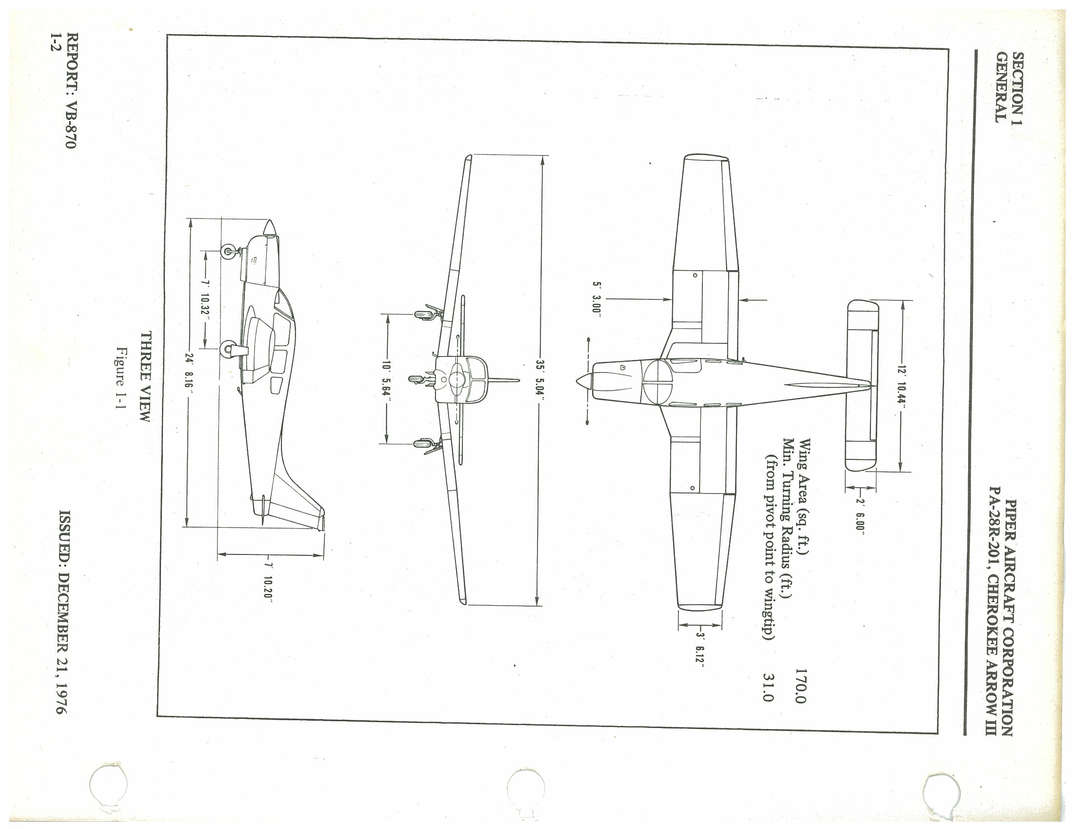
Three View Dimensions p. 11
| Dimension | Value |
|---|---|
| Wingspan | 35' 5.04" |
| Horizontal stabilizer span | 12' 10.44" |
| Horizontal stabilizer chord | 2' 6.00" |
| Overall length | 24' 8.16" |
| Overall height | 7' 10.20" |
| Main gear track (wheel centerline) | 10' 5.64" |
| Nose gear to main gear (wheelbase) | 7' 10.32" |
| Wing chord (at fuselage) | 5' 3.00" |
| Wing tip chord | 3' 6.12" |
| Wing area | 170.0 sq. ft. |
| Min. turning radius (pivot point to wingtip) | 31.0 ft. |
1.3 Engines p. 12
| Parameter | Value |
|---|---|
| (a) Number of Engines | 1 |
| (b) Engine Manufacturer | Lycoming |
| (c) Engine Model Number | IO-360-C1C6 |
| (d) Rated Horsepower | 200 |
| (e) Rated Speed (rpm) | 2700 |
| (f) Bore (inches) | 5.125 |
| (g) Stroke (inches) | 4.375 |
| (h) Displacement (cubic inches) | 361.0 |
| (i) Compression Ratio | 8.7:1 |
| (j) Engine Type | Four Cylinder, Direct Drive, Horizontally Opposed, Air Cooled |
1.5 Propellers
| Parameter | McCauley | Hartzell |
|---|---|---|
| (a) Number of Propellers | 1 | 1 |
| (b) Propeller Manufacturer | McCauley | Hartzell |
| (c) Blade Model | 90DHA-16 | F7666A-2R |
| (d) Number of Blades | 2 | 2 |
| (e) Hub Model | B2D34C213 | HC-C2YK-1( )F/ |
| (f1) Propeller Diameter — Maximum (inches) | 74 | 74 |
| (f2) Propeller Diameter — Minimum (inches) | 73 | 72 |
| (g) Propeller Type | Constant Speed, Hydraulically Actuated | |
1.7 Fuel
| Parameter | Value |
|---|---|
| (a) Fuel Capacity (U.S. gal) (total) | 77 |
| (b) Usable Fuel (U.S. gal) (total) | 72 |
| (c1) Fuel Grade, Aviation — Minimum Octane | Grade 100 |
| (c2) Specified Octane | 100 Green or 100LL Blue |
| (c3) Alternate Fuels | 100/130 Green — Refer to Fuel Requirements, Section 8.21 (b) |
1.9 Oil p. 13
| Parameter | Value |
|---|---|
| (a) Oil Capacity (U.S. quarts) | 8 |
| (b) Oil Specifications | Refer to latest issue of Lycoming Service Instruction 1014 |
(c) Oil Viscosity per Average Ambient Temperature for Starting
| Average Ambient Temperature | MIL-L-6082B SAE Grade |
MIL-L-22851 Ashless Dispersant SAE Grades |
|---|---|---|
| All Temperatures | — | 15W-50 or 20W-50 |
| Above 80°F | 60 | 60 |
| Above 60°F | 50 | 40 or 50 |
| 30°F to 90°F | 40 | 40 |
| 0°F to 70°F | 30 | 30, 40 or 20W-40 |
| Below 10°F | 20 | 30 or 20W-30 |
1.11 Maximum Weights
| Parameter | Weight (lbs) |
|---|---|
| (a) Maximum Takeoff Weight | 2750 |
| (b) Maximum Landing Weight | 2750 |
| (c) Maximum Weight in Baggage Compartment | 200 |
1.13 Standard Airplane Weights*
| Parameter | Weight (lbs) |
|---|---|
| (a) Standard Empty Weight — Weight of a standard airplane including unusable fuel, full operating fluids and full oil | 1622 |
| (b) Maximum Useful Load — The difference between the Maximum Takeoff Weight and the Standard Empty Weight | 1128 |
1.15 Baggage Space
| Parameter | Value |
|---|---|
| (a) Compartment Volume (cubic feet) | 24 |
| (b) Entry Width (inches) | 22 |
| (c) Entry Height (inches) | 20 |
1.17 Specific Loadings
| Parameter | Value |
|---|---|
| (a) Wing Loading (lbs per sq ft) | 16.18 |
| (b) Power Loading (lbs per hp) | 13.75 |
1.19 Symbols, Abbreviations and Terminology p. 14
The following definitions are of symbols, abbreviations and terminology used throughout the handbook and those which may be of added operational significance to the pilot.
(a) General Airspeed Terminology and Symbols
| Symbol | Definition |
|---|---|
| CAS | Calibrated Airspeed means the indicated speed of an aircraft, corrected for position and instrument error. Calibrated airspeed is equal to true airspeed in standard atmosphere at sea level. |
| KCAS | Calibrated Airspeed expressed in "Knots." |
| GS | Ground Speed is the speed of an airplane relative to the ground. |
| IAS | Indicated Airspeed is the speed of an aircraft as shown on the airspeed indicator when corrected for instrument error. IAS values published in this handbook assume zero instrument error. |
| KIAS | Indicated Airspeed expressed in "Knots." |
| M | Mach Number is the ratio of true airspeed to the speed of sound. |
| TAS | True Airspeed is the airspeed of an airplane relative to undisturbed air which is the CAS corrected for altitude, temperature and compressability. |
| VA | Maneuvering Speed is the maximum speed at which application of full available aerodynamic control will not overstress the airplane. |
| VFE | Maximum Flap Extended Speed is the highest speed permissible with wing flaps in a prescribed extended position. |
| VLE | Maximum Landing Gear Extended Speed is the maximum speed at which an aircraft can be safely flown with the landing gear extended. |
| VLO | Maximum Landing Gear Operating Speed is the maximum speed at which the landing gear can be safely extended or retracted. |
| VNE/MNE | Never Exceed Speed or Mach Number is the speed limit that may not be exceeded at any time. |
| VNO | Maximum Structural Cruising Speed is the speed that should not be exceeded except in smooth air and then only with caution. |
| VS | Stalling Speed or the minimum steady flight speed at which the airplane is controllable. |
| VSO | Stalling Speed or the minimum steady flight speed at which the airplane is controllable in the landing configuration. |
| VX | Best Angle-of-Climb Speed is the airspeed which delivers the greatest gain of altitude in the shortest possible horizontal distance. |
| VY | Best Rate-of-Climb Speed is the airspeed which delivers the greatest gain in altitude in the shortest possible time. |
(b) Meteorological Terminology
| ISA |
International Standard Atmosphere in which: The air is a dry perfect gas; The temperature at sea level is 15° Celsius (59° Fahrenheit); The pressure at sea level is 29.92 inches hg. (1013 mb); The temperature gradient from sea level to the altitude at which the temperature is -56.5°C (-69.7°F) is -0.00198°C (-0.003566°F) per foot and zero above that altitude. |
| OAT | Outside Air Temperature is the free air static temperature, obtained either from inflight temperature indications or ground meteorological sources, adjusted for instrument error and compressibility effects. |
| Indicated Pressure Altitude | The number actually read from an altimeter when the barometric subscale has been set to 29.92 inches of mercury (1013 millibars). |
| Pressure Altitude | Altitude measured from standard sea-level pressure (29.92 in. Hg) by a pressure or barometric altimeter. It is the indicated pressure altitude corrected for position and instrument error. In this handbook, altimeter instrument errors are assumed to be zero. |
| Station Pressure | Actual atmospheric pressure at field elevation. |
| Wind | The wind velocities recorded as variables on the charts of this handbook are to be understood as the headwind or tailwind components of the reported winds. |
(c) Power Terminology p. 16
| Takeoff Power | Maximum power permissible for takeoff. |
| Maximum Continuous Power | Maximum power permissible continuously during flight. |
| Maximum Climb Power | Maximum power permissible during climb. |
| Maximum Cruise Power | Maximum power permissible during cruise. |
(d) Engine Instruments
| EGT Gauge | Exhaust Gas Temperature Gauge |
(e) Airplane Performance and Flight Planning Terminology
| Climb Gradient | The demonstrated ratio of the change in height during a portion of a climb, to the horizontal distance traversed in the same time interval. |
| Demonstrated Crosswind Velocity | The demonstrated crosswind velocity is the velocity of the crosswind component for which adequate control of the airplane during takeoff and landing was actually demonstrated during certification tests. |
| Accelerate-Stop Distance | The distance required to accelerate an airplane to a specified speed and, assuming failure of an engine at the instant that speed is attained, to bring the airplane to a stop. |
| MEA | Minimum en route IFR altitude. |
| Route Segment | A part of a route. Each end of that part is identified by: (1) a geographical location; or (2) a point at which a definite radio fix can be established. |
(f) Weight and Balance Terminology p. 17
| Reference Datum | An imaginary vertical plane from which all horizontal distances are measured for balance purposes. |
| Station | A location along the airplane fuselage usually given in terms of distance from the reference datum. |
| Arm | The horizontal distance from the reference datum to the center of gravity (C.G.) of an item. |
| Moment | The product of the weight of an item multiplied by its arm. (Moment divided by a constant is used to simplify balance calculations by reducing the number of digits.) |
| Center of Gravity (C.G.) | The point at which an airplane would balance if suspended. Its distance from the reference datum is found by dividing the total moment by the total weight of the airplane. |
| C.G. Arm | The arm obtained by adding the airplane's individual moments and dividing the sum by the total weight. |
| C.G. Limits | The extreme center of gravity locations within which the airplane must be operated at a given weight. |
| Usable Fuel | Fuel available for flight planning. |
| Unusable Fuel | Fuel remaining after a runout test has been completed in accordance with governmental regulations. |
| Standard Empty Weight | Weight of a standard airplane including unusable fuel, full operating fluids and full oil. |
| Basic Empty Weight | Standard empty weight plus optional equipment. |
| Payload | Weight of occupants, cargo and baggage. |
| Useful Load | Difference between takeoff weight, or ramp weight if applicable, and basic empty weight. |
| Maximum Ramp Weight | Maximum weight approved for ground maneuver. (It includes weight of start, taxi and run up fuel.) |
| Maximum Takeoff Weight | Maximum weight approved for the start of the takeoff run. |
| Maximum Landing Weight | Maximum weight approved for the landing touchdown. |
| Maximum Zero Fuel Weight | Maximum weight exclusive of usable fuel. |
p. 18 — This page intentionally left blank
p. 19 — This page intentionally left blank
1.21 Conversion Factors p. 20
| Multiply | By | To Obtain |
|---|---|---|
| acres | 0.4047 | ha |
| 43560 | sq. ft. | |
| 0.0015625 | sq. mi. | |
| atmospheres (atm) | 76 | cm Hg |
| 29.92 | in. Hg | |
| 1.0133 | bar | |
| 1.033 | kg/cm² | |
| 14.70 | lb./sq. in. | |
| 2116 | lb./sq. ft. | |
| bars (bar) | 0.98692 | atm. |
| 14.503768 | lb./sq. in. | |
| British Thermal Unit (BTU) | 0.2519958 | kg-cal |
| centimeters (cm) | 0.3937 | in. |
| 0.032808 | ft. | |
| centimeters of mercury at 0°C (cm Hg) | 0.01316 | atm |
| 0.3937 | in. Hg | |
| 0.1934 | lb./sq. in. | |
| 27.85 | lb./sq. ft. | |
| 135.95 | kg/m² | |
| centimeters per second (cm/sec.) | 0.032808 | ft./sec. |
| 1.9685 | ft./min. | |
| 0.02237 | mph | |
| cubic centimeters (cm³) | 0.03381 | fl. oz. |
| 0.06102 | cu. in. | |
| 3.531 × 10⁻⁵ | cu. ft. | |
| 0.001 | l | |
| 2.642 × 10⁻⁴ | U.S. gal. | |
| cubic feet (cu. ft.) | 28317 | cm³ |
| 0.028317 | m³ | |
| 1728 | cu. in. | |
| 0.037037 | cu. yd. | |
| 7.481 | U.S. gal. | |
| 28.32 | l | |
| cubic feet per minute (cu. ft./min.) | 0.472 | l/sec. |
| 0.028317 | m³/min. | |
| cubic inches (cu. in.) | 16.39 | cm³ |
| 1.639 × 10⁻⁵ | m³ | |
| 5.787 × 10⁻⁴ | cu. ft. | |
| 0.5541 | fl. oz. | |
| 0.01639 | l | |
| 4.329 × 10⁻³ | U.S. gal. | |
| 0.01732 | U.S. qt. | |
| cubic meters (m³) | 61024 | cu. in. |
| 1.308 | cu. yd. | |
| 35.3147 | cu. ft. | |
| 264.2 | U.S. gal. | |
| cubic meters per minute (m³/min.) | 35.3147 | cu. ft./min. |
| cubic yards (cu. yd.) | 27 | cu. ft. |
| 0.7646 | m³ | |
| 202 | U.S. gal. | |
| degrees (arc) | 0.01745 | radians |
| degrees per second (deg./sec.) | 0.01745 | radians/sec. |
| drams, fluid (dr. fl.) | 0.125 | fl. oz. |
| drams, avdp. (dr. avdp.) | 0.0625 | oz. avdp. |
| feet (ft.) | 30.48 | cm |
| 0.3048 | m | |
| 12 | in. | |
| 0.33333 | yd. | |
| 0.0606061 | rod | |
| 1.894 × 10⁻⁴ | mi. | |
| 1.645 × 10⁻⁴ | NM | |
| feet per minute (ft./min.) | 0.01136 | mph |
| 0.01829 | km/hr. | |
| 0.508 | cm/sec. | |
| 0.00508 | m/sec. |
| MULTIPLY | BY | TO OBTAIN |
|---|---|---|
| feet per second (ft./sec.) | 0.6818 | mph |
| 1.097 | km/hr. | |
| 30.48 | cm/sec. | |
| 0.5921 | kts. | |
| foot-pounds (ft.-lb.) | 0.138255 | m-kg |
| 3.24 × 10⁻⁴ | kg-cal | |
| foot-pounds per minute (ft.-lb./min.) | 3.030 × 10⁻⁵ | hp |
| foot-pounds per second (ft.-lb./sec.) | 1.818 × 10⁻⁵ | hp |
| gallons, Imperial (Imperial gal.) | 277.4 | cu. in. |
| 1.201 | U.S. gal. | |
| 4.546 | l | |
| gallons, U.S. dry (U.S. gal. dry) | 268.8 | cu. in. |
| 1.556 × 10⁻¹ | cu. ft. | |
| 1.164 | U.S. gal. | |
| 4.405 | l | |
| gallons, U.S. liquid (U.S. gal.) | 231 | cu. in. |
| 0.1337 | cu. ft. | |
| 4.951 × 10⁻³ | cu. yd. | |
| 3785.4 | cm3 | |
| 3.785 × 10⁻³ | m3 | |
| 3.785 | l | |
| 0.83268 | Imperial gal. | |
| 128 | fl. oz. | |
| gallons per acre (gal./acre) | 9.353 | l/ha |
| grams (g) | 0.001 | kg |
| 0.3527 | oz. avdp. | |
| 2.205 × 10⁻³ | lb. | |
| grams per centimeter (g/cm) | 0.1 | kg/m |
| 6.721 × 10⁻² | lb./ft. | |
| 5.601 × 10⁻³ | lb./in. | |
| grams per cubic centimeter (g/cm3) | 1000 | kg/m3 |
| 0.03613 | lb./cu. in. | |
| 62.43 | lb./cu. ft. | |
| hectares (ha) | 2.471 | acres |
| 107639 | sq. ft. | |
| 10000 | m2 | |
| horsepower (hp) | 33000 | ft.-lb./min. |
| 550 | ft.-lb./sec. | |
| 76.04 | m-kg/sec. | |
| 1.014 | metric hp | |
| horsepower, metric | 75 | m-kg/sec. |
| 0.9863 | hp | |
| inches (in.) | 25.40 | mm |
| 2.540 | cm | |
| 0.0254 | m | |
| 0.08333 | ft. | |
| 0.027777 | yd. | |
| inches of mercury at 0°C (in. Hg) | 0.033421 | atm |
| 0.4912 | lb./sq. in. | |
| 70.73 | lb./sq. ft. | |
| 345.3 | kg/m2 | |
| 2.540 | cm Hg | |
| 25.40 | mm Hg | |
| inch-pounds (in.-lb.) | 0.011521 | m-kg |
| kilograms (kg) | 2.204622 | lb. |
| 35.27 | oz. avdp. | |
| 1000 | g | |
| kilogram-calories (kg-cal) | 3.9683 | BTU |
| 3087 | ft.-lb. | |
| 426.9 | m-kg | |
| kilograms per cubic meter (kg/m3) | 0.06243 | lb./cu. ft. |
| 0.001 | g/cm3 | |
| kilograms per hectare (kg/ha) | 0.892 | lb./acre |
| kilograms per square centimeter (kg/cm2) | 0.9678 | atm |
| 28.96 | in. Hg | |
| 14.22 | lb./sq. in. | |
| 2048 | lb./sq. ft. |
p. 22
| MULTIPLY | BY | TO OBTAIN |
|---|---|---|
| kilograms per square meter (kg/m2) | 2.896 × 10⁻³ | in. Hg |
| 1.422 × 10⁻³ | lb./sq. in. | |
| 0.2048 | lb./sq. ft. | |
| kilometers (km) | 1 × 10⁻⁵ | cm |
| 3280.8 | ft. | |
| 0.6214 | mi. | |
| 0.53996 | NM | |
| kilometers per hour (km/hr.) | 0.9113 | ft./sec. |
| 58.68 | ft./min. | |
| 0.53996 | kt | |
| 0.6214 | mph | |
| 0.27778 | m/sec. | |
| 16.67 | m/min. | |
| knots (kt) | 1 | nautical mph |
| 1.689 | ft./sec. | |
| 1.1516 | statute mph | |
| 1.852 | km/hr. | |
| 51.48 | m/sec. | |
| liters (l) | 1000 | cm3 |
| 61.02 | cu. in. | |
| 0.03531 | cu. ft. | |
| 33.814 | fl. oz. | |
| 0.264172 | U.S. gal. | |
| 0.2200 | Imperial gal. | |
| 1.05669 | qt. | |
| liters per hectare (l/ha) | 13.69 | fl. oz./acre |
| 0.107 | gal./acre | |
| liters per second (l/sec.) | 2.12 | cu. ft./min. |
| meters (m) | 39.37 | in. |
| 3.280840 | ft. | |
| 1.0936 | yd. | |
| 0.198838 | rod | |
| 6.214 × 10⁻⁴ | mi. | |
| 5.3996 × 10⁻⁴ | NM | |
| meter-kilogram (m-kg) | 7.23301 | ft.-lb. |
| 86.798 | in.-lb. | |
| meters per minute (m/min.) | 0.06 | km/hr. |
| meters per second (m/sec.) | 3.280840 | ft./sec. |
| 196.8504 | ft./min. | |
| 2.237 | mph | |
| 3.6 | km/hr. | |
| microns | 3.937 × 10⁻⁵ | in. |
| miles, statute (mi.) | 5280 | ft. |
| 1.6093 | km | |
| 1609.3 | m | |
| 0.8684 | NM | |
| miles per hour (mph) | 44.7041 | cm/sec. |
| 4.470 × 10⁻¹ | m/sec. | |
| 1.467 | ft./sec. | |
| 88 | ft./min. | |
| 1.6093 | km/hr. | |
| 0.8684 | kt | |
| miles per hour square (m/hr. sq.) | 2.151 | ft./sec. sq. |
| millibars | 2.953 × 10⁻² | in. Hg |
| millimeters (mm) | 0.03937 | in. |
| millimeters of mercury at 0°C (mm Hg) | 0.03937 | in. Hg |
| nautical miles (NM) | 6080 | ft. |
| 1.1516 | statute mi. | |
| 1852 | m | |
| 1.852 | km | |
| ounces, avdp. (oz. avdp.) | 28.35 | g |
| 16 | dr. avdp. | |
| ounces, fluid (fl. oz.) | 8 | dr. fl. |
| 29.57 | cm3 | |
| 1.805 | cu. in. | |
| 0.0296 | l | |
| 0.0078 | U.S. gal. |
(Continued from previous page — Section 1 General: Unit Conversion Table)
| Multiply | By | To Obtain | Multiply | By | To Obtain |
|---|---|---|---|---|---|
| ounces, fluid per acre (fl. oz./acre) | 0.073 | l/ha | rod | 16.5 5.5 5.029 |
ft. yd. m |
| pounds (lb.) | 0.453592 453.6 3.108 × 10⁻² |
kg g slug |
slug | 32.174 | lb. |
| pounds per acre (lb./acre) | 1.121 | kg/ha | square centimeters (cm²) | 0.1550 0.001076 |
sq. in. sq. ft. |
| pounds per cubic foot (lb./cu. ft.) | 16.02 | kg/m³ | square feet (sq. ft.) | 929 0.092903 144 0.1111 2.296 × 10⁻⁵ |
cm² m² sq. in. sq. yd. acres |
| pounds per cubic inch (lb./cu. in.) | 1728 27.68 |
lb./cu. ft. g/cm³ |
square inches (sq. in.) | 6.4516 6.944 × 10⁻³ |
cm² sq. ft. |
| pounds per square foot (lb./sq. ft.) | 0.1414 4.88243 4.725 × 10⁻⁴ |
in. Hg kg/m² atm |
square kilometers (km²) | 0.3861 | sq. mi. |
| pounds per square inch (psi or lb./sq. in.) | 5.1715 2.036 0.06804 0.0689476 703.1 |
cm Hg in. Hg atm bar kg/m² |
square meters (m²) | 10.76391 1.196 0.0001 |
sq. ft. sq. yd. ha |
| quart, U.S. (qt.) | 0.94635 57.749 |
l cu. in. |
square miles (sq. mi.) | 2.590 640 |
km² acres |
| radians | 57.30 0.1592 |
deg. (arc) rev. |
square rods (sq. rods) | 30.25 | sq. yd. |
| radians per second (radians/sec.) | 57.30 0.1592 9.549 |
deg./sec. rev./sec. rpm |
square yards (sq. yd.) | 0.8361 9 0.0330579 |
m² sq. ft. sq. rods |
| revolutions (rev.) | 6.283 | radians | yards (yd.) | 0.9144 3 36 0.181818 |
m ft. in. rod |
| revolutions per minute (rpm or rev./min.) | 0.1047 | radians/sec. | |||
| revolutions per second (rev./sec.) | 6.283 | radians/sec. |
Section 2 — Limitations p. 24
Table of Contents
| Paragraph No. | Title | Page No. |
|---|---|---|
| 2.1 | General | 2-1 |
| 2.3 | Airspeed Limitations | 2-1 |
| 2.5 | Airspeed Indicator Markings | 2-2 |
| 2.7 | Power Plant Limitations | 2-2 |
| 2.9 | Power Plant Instrument Markings | 2-3 |
| 2.11 | Weight Limits | 2-3 |
| 2.13 | Center of Gravity Limits | 2-4 |
| 2.15 | Maneuver Limits | 2-4 |
| 2.17 | Flight Load Factors | 2-4 |
| 2.19 | Types of Operations | 2-4 |
| 2.21 | Fuel Limitations | 2-5 |
| 2.23 | Placards | 2-5 |
2.1 General p. 25
This section provides the "FAA Approved" operating limitations, instrument markings, color coding and basic placards necessary for operation of the airplane and its systems.
Limitations associated with those optional systems and equipment which require handbook supplements can be found in Section 9 (Supplements).
2.3 Airspeed Limitations
| Speed | KIAS | KCAS |
|---|---|---|
| Never Exceed Speed (VNE) — Do not exceed this speed in any operation. | 183 | 186 |
| Maximum Structural Cruising Speed (VNO) — Do not exceed this speed except in smooth air and then only with caution. | 146 | 148 |
| Design Maneuvering Speed (VA) — Do not make full or abrupt control movements above this speed. At 2750 LBS. G.W. At 1865 LBS. G.W. |
118 96 |
120 96 |
| Maximum Flaps Extended Speed (VFE) — Do not exceed this speed with the flaps extended. | 103 | 103 |
| Maximum Landing Gear Extension Speed — Do not exceed this speed when extending the landing gear. | 129 | 130 |
| Maximum Landing Gear Retraction Speed — Do not exceed this speed when retracting the landing gear. | 107 | 107 |
| Maximum Landing Gear Extended Speed (VLE) — Do not exceed this speed with the landing gear extended. | 129 | 130 |
2.5 Airspeed Indicator Markings p. 26
| Marking | KIAS |
|---|---|
| Red Radial Line (Never Exceed) | 183 |
| Yellow Arc (Caution Range – Smooth Air Only) | 146 to 183 |
| Green Arc (Normal Operating Range) | 60 to 146 |
| White Arc (Flap Down) | 55 to 103 |
2.7 Power Plant Limitations
| Item | McCauley | Hartzell |
|---|---|---|
| (a) Number of Engines | 1 | |
| (b) Engine Manufacturer | Lycoming | |
| (c) Engine Model No. | IO-360-C1C6 | |
| (d) Engine Operating Limits | ||
| (1) Maximum Horsepower | 200 | |
| (2) Maximum Rotation Speed (RPM) | 2700 | |
| (3) Maximum Oil Temperature | 245°F | |
| (e) Oil Pressure | ||
| Minimum (red line) | 25 PSI | |
| Maximum (red line) | 90 PSI | |
| (f) Fuel Pressure | ||
| Minimum (red line) | 14 PSI | |
| Maximum (red line) | 45 PSI | |
| (g) Fuel Grade (minimum octane) | Aviation Grade 100 | |
| (h) Number of Propellers | 1 | |
| (i) Propeller Manufacturer | McCauley | Hartzell |
| (j) Propeller Hub and Blade Model | B2D34C213/90DHA-16 | HC-C2YK-1( )F/F7666A-2R |
| (k) Propeller Diameter | ||
| Minimum | 73 IN. | 72 IN. |
| Maximum | 74 IN. | 74 IN. |
| (l) Blade Angle Limits | ||
| Low Pitch Stop | 12.5° ± 0.2° | 14.0° ± 0.2° |
| High Pitch Stop | 29.8° ± 0.5° | 29.0° ± 2.0° |
| (m) RPM Restriction (McCauley Prop Only) | Avoid continuous operation between 1500 and 1950 RPM below 15" manifold pressure | |
2.9 Power Plant Instrument Markings p. 27
| Instrument / Marking | Value |
|---|---|
| (a) Tachometer | |
| Green Arc (Normal Operating Range) | 500 to 2700 RPM |
| Red Line (Maximum Continuous Power) | 2700 RPM |
| (b) Oil Temperature | |
| Green Arc (Normal Operating Range) | 75 to 245°F |
| Red Line (Maximum) | 245°F |
| (c) Oil Pressure | |
| Green Arc (Normal Operating Range) | 60 PSI to 90 PSI |
| Yellow Arc (Caution Range) (Idle) | 25 PSI to 60 PSI |
| Yellow Arc (Caution Range) (Start and Warm Up) | 90 PSI to 100 PSI |
| Red Line (Minimum) | 25 PSI |
| Red Line (Maximum) | 90 PSI |
| (d) Fuel Pressure | |
| Green Arc (Normal Operating Range) | 14 PSI to 45 PSI |
| Red Line (Minimum) | 14 PSI |
| Red Line (Maximum) | 45 PSI |
2.11 Weight Limits
| Item | Limit |
|---|---|
| (a) Maximum Weight | 2750 LBS |
| (b) Maximum Baggage | 200 LBS |
2.13 Center of Gravity Limits p. 28
| Weight (Pounds) | Forward Limit Inches Aft of Datum |
Rearward Limit Inches Aft of Datum |
|---|---|---|
| 2750 | 88.9 | 91.5 |
| 2375 & below | 82 | 91.5 |
- Straight line variation between points given.
- The datum used is 78.4 inches ahead of the wing leading edge at the inboard intersection of the straight and tapered section.
- It is the responsibility of the airplane owner and the pilot to insure that the airplane is properly loaded. See Section 6 (Weight and Balance) for proper loading instructions.
2.15 Maneuver Limits
No acrobatic maneuvers including spins approved.
2.17 Flight Load Factors
| Item | Limit |
|---|---|
| (a) Positive Load Factor (Maximum) | 3.8 G |
| (b) Negative Load Factor (Maximum) | No inverted maneuvers approved |
2.19 Types of Operations
The airplane is approved for the following operations when equipped in accordance with FAR 91 or FAR 135.
- (a) Day V.F.R.
- (b) Night V.F.R.
- (c) Day I.F.R.
- (d) Night I.F.R.
- (e) Non Icing
2.21 Fuel Limitations p. 29
| Item | Quantity |
|---|---|
| (a) Total Capacity | 77 U.S. GAL |
|
(b) Unusable Fuel The unusable fuel for this airplane has been determined as 2.5 gallons in each wing in critical flight attitudes. |
5 U.S. GAL |
|
(c) Usable Fuel The usable fuel in this airplane has been determined as 36.0 gallons in each wing tank. |
72 U.S. GAL |
2.23 Placards
In full view of the pilot:
"THIS AIRPLANE MUST BE OPERATED AS A NORMAL CATEGORY AIRPLANE IN COMPLIANCE WITH THE OPERATING LIMITATIONS STATED IN THE FORM OF PLACARDS, MARKINGS AND MANUALS."
"THIS AIRCRAFT APPROVED FOR NIGHT I.F.R. NON-ICING FLIGHT WHEN EQUIPPED IN ACCORDANCE WITH FAR 91 OR FAR 135."
In full view of the pilot, the following takeoff and landing check lists will be installed:
Takeoff Check List (Placard)
| Fuel on Proper Tank | Mixture - Set | Flaps - Set |
| Electric Fuel Pump - On | Propeller - Set | Trim Tab - Set |
| Engine Gauges - Checked | Fasten Belts/Harness | Controls - Free |
| Alternate Air - Closed | Doors - Latched | |
| Seat Backs Erect | Air Conditioner - Off |
Landing Check List (Placard)
| Fuel on Proper Tank | Electric Fuel Pump - On | Gear Down (129 KIAS Max) |
| Seat Backs Erect | Mixture - Rich | Flaps - Set (103 KIAS Max) |
| Fasten Belts/Harness | Propeller - Set | Air Conditioner - Off |
On the instrument panel in full view of the pilot:
"NO ACROBATIC MANEUVERS, INCLUDING SPINS APPROVED."
Gear Warning System p. 32
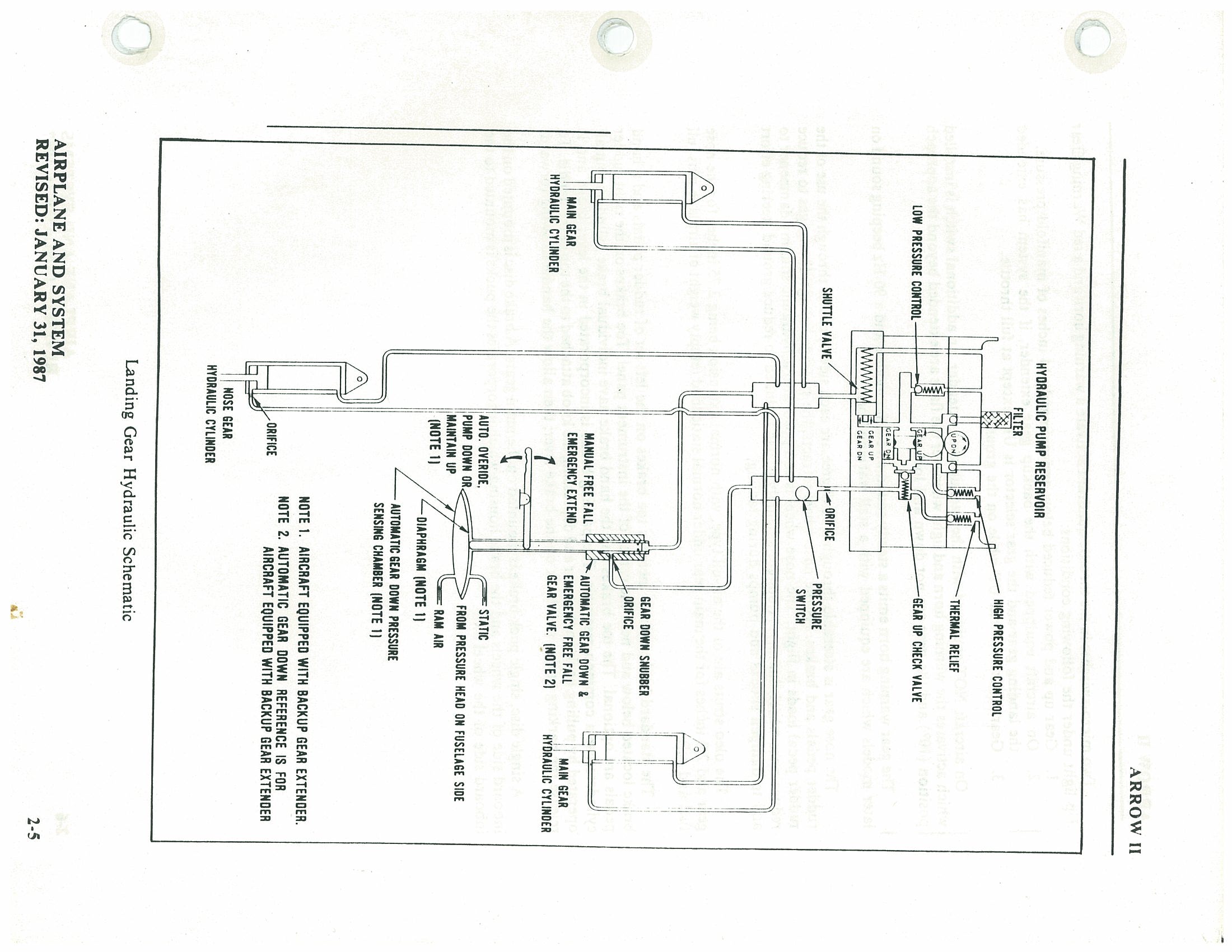
Two micro-switches in the throttle quadrant activate a warning horn and a red Warning Gear Up light under the following conditions:
- Gear up and power reduced below approximately 14 inches of manifold pressure.
- On aircraft equipped with the backup gear extender, if the system has extended the landing gear and the gear selector is UP, except at full throttle.
- Gear selector switch UP while on the ground.
The gear warning horn emits a steady sound on earlier models and a 90 Hz beeping sound on later models which are equipped with a stall warning horn.
Nose Gear Steering
The nose gear is steerable through a 30 degree arc each side of center through the use of the rudder pedals and brakes. As the nose wheel retracts, the steerage linkage disengages to reduce rudder pedal loads in flight. The nose wheel is equipped with a hydraulic shimmy dampener to reduce nose wheel shimmy. A bungee assembly is also included to reduce ground steering effort and to dampen shocks and bumps during taxiing.
Oleo Struts
The oleo struts are of the air-oil type, with normal extension being 2.75 inches for the nose gear and 2.0 inches for the main gear under normal static load (empty weight of airplane plus full fuel and oil).
Brake System
The standard brake system includes toe brakes on the left set of rudder pedals and a hand brake located below and near the center of the instrument panel. Toe brakes on the right rudder pedals are optional. The toe brakes and the hand brake have individual brake cylinders, but all cylinders use a common reservoir. The parking brake is incorporated in the lever brake and is operated by pulling back on the lever and depressing the knob attached to the top of the handle. To release the parking brake, pull back on the brake lever; then allow the handle to swing forward.
A single disc, single puck brake is mounted on the main gears. A brake disc is mounted on the inboard side of the wheels and the brake housing which incorporates the pucks is mounted to the inboard side of the wheel axle.
Cockpit Placards p. 33
On the instrument panel in full view of the pilot:
118 KIAS AT 2750 LBS (SEE P.O.H.)"
| "GEAR DOWN | 129 KIAS (MAX)" |
| "GEAR UP | 107 KIAS (MAX)" |
| "EXTENDED | 129 KIAS (MAX)" |
Near emergency gear lever:
Near emergency gear lever (aircraft equipped with backup gear extender):
LOCK PIN ON SIDE
TO ENGAGE OVERRIDE:
PULL LEVER FULL UP, PUSH LOCK PIN
TO RELEASE OVERRIDE:
PULL LEVER FULL UP & RELEASE"
Near gear selector switch:
| "GEAR UP | 107 KIAS MAX" |
| "DOWN | 129 KIAS MAX" |
Adjacent to upper door latch (front and rear doors):
On the instrument panel in full view of the pilot:
In full view of pilot and over the fuel quantity gauges:
"FUEL REMAINING WHEN QUANTITY INDICATOR READS ZERO CANNOT BE USED SAFELY IN FLIGHT."
In full view of the pilot, in the area of the air conditioner controls when the air conditioner is installed:
"WARNING – AIR CONDITIONER MUST BE OFF TO INSURE NORMAL TAKEOFF CLIMB PERFORMANCE."
On inside of baggage compartment door:
"BAGGAGE MAXIMUM 200 LBS. SEE WEIGHT AND BALANCE DATA FOR BAGGAGE BETWEEN 150 LBS. AND 200 LBS."
Adjacent to fuel tank filler caps:
"FUEL – 100/130 AVIATION GRADE MIN. – USABLE CAPACITY 36 GAL."
"USABLE CAPACITY TO BOTTOM OF FILLER NECK INDICATOR 25 GAL."
On the instrument panel in full view of the pilot when McCauley propeller is installed:
"AVOID CONTINUOUS OPERATION BETWEEN 1500 AND 1950 RPM BELOW 15" MANIFOLD PRESSURE."
Section 3 — Emergency Procedures p. 35
Table of Contents
| Paragraph No. | Subject | Page No. |
|---|---|---|
| 3.1 | General | 3-1 |
| 3.3 | Emergency Procedures Check List | 3-3 |
| Engine Fire During Start | 3-3 | |
| Engine Power Loss During Takeoff | 3-3 | |
| Engine Power Loss On Flight | 3-3 | |
| Power Off Landing | 3-3 | |
| Fire In Flight | 3-3 | |
| Loss of Oil Pressure | 3-4 | |
| Loss of Fuel Pressure | 3-4 | |
| High Oil Temperature | 3-4 | |
| Alternator Failure | 3-4 | |
| Propeller Overspeed | 3-4 | |
| Emergency Landing Gear Extension | 3-4 | |
| Spin Recovery | 3-4 | |
| Open Door | 3-5 | |
| 3.5 | Amplified Emergency Procedures (General) | 3-7 |
| 3.7 | Engine Fire During Start | 3-7 |
| 3.9 | Engine Power Loss During Takeoff | 3-7 |
| 3.11 | Engine Power Loss In Flight | 3-8 |
| 3.13 | Power Off Landing | 3-9 |
| 3.15 | Fire In Flight | 3-10 |
| 3.17 | Loss of Oil Pressure | 3-11 |
| 3.19 | Loss of Fuel Pressure | 3-11 |
| 3.21 | High Oil Temperature | 3-11 |
| 3.23 | Alternator Failure | 3-12 |
| 3.25 | Propeller Overspeed | 3-12 |
| 3.27 | Emergency Landing Gear Extension | 3-12 |
| 3.29 | Spin Recovery | 3-13 |
| 3.31 | Open Door | 3-13 |
| 3.33 | Engine Roughness | 3-13 |
3.1 General p. 36
This section provides the recommended procedures for coping with various emergency or critical situations. All of the emergency procedures required by the FAA as well as those necessary for operation of the airplane, as determined by the operating and design features of the airplane, are presented.
Emergency procedures associated with optional systems and equipment which require handbook supplements are presented in Section 9, Supplements.
This section is divided into two basic parts. The first part contains the emergency procedures checklists. These checklists supply an immediate action sequence to be followed during critical situations with little emphasis on the operation of the systems.
The second part of the section provides amplified emergency procedures corresponding to the emergency procedures checklist items. These amplified emergency procedures contain additional information to provide the pilot with a more complete description of the procedures so they may be more easily understood.
Pilots must familiarize themselves with the procedures given in this section and must be prepared to take the appropriate action should an emergency situation arise. The procedures are offered as a course of action for coping with the particular situation or condition described. They are not a substitute for sound judgement and common sense.
Most basic emergency procedures are a normal part of pilot training. The information presented in this section is not intended to replace this training. This information is intended to provide a source of reference for the procedures which are applicable to this airplane. The pilot should review standard emergency procedures periodically to remain proficient in them.
3.3 Emergency Procedures Check List p. 38
Engine Fire During Start
- Starter — crank engine
- Mixture — idle cut-off
- Throttle — open
- Electric fuel pump — OFF
- Fuel selector — OFF
- Abandon if fire continues
Engine Power Loss During Takeoff
If sufficient runway remains for a normal landing, leave gear down and land straight ahead.
If area ahead is rough, or if it is necessary to clear obstructions:
- Gear selector switch — UP
- Emergency gear lever (on aircraft equipped with backup gear extender) — locked in OVERRIDE ENGAGED position
If sufficient altitude has been gained to attempt a restart:
- Maintain safe airspeed
- Fuel selector — switch to tank containing fuel
- Electric fuel pump — check ON
- Mixture — check RICH
- Alternate air — OPEN
- Emergency gear lever — as required
- If power is not regained, proceed with power off landing.
Engine Power Loss in Flight
- Fuel selector — switch to tank containing fuel
- Electric fuel pump — ON
- Mixture — RICH
- Alternate air — OPEN
- Engine gauges — check for indication of cause of power loss
- If no fuel pressure is indicated, check tank selector position to be sure it is on a tank containing fuel.
When power is restored:
- Alternate air — CLOSED
- Electric fuel pump — OFF
If power is not restored, prepare for power off landing.
Trim for 79 KIAS
Power Off Landing
- Trim for 79 KIAS
- Locate suitable field
- Establish spiral pattern
- 1000 ft above field at downwind position for normal landing approach
- When field can easily be reached, slow to 72 KIAS for shortest landing
- Touchdowns should normally be made at lowest possible airspeed with full flaps
When committed to landing:
- Ignition — OFF
- Master switch — OFF
- Fuel selector — OFF
- Mixture — idle cut-off
- Seat belt and harness — tight
Fire in Flight
- Source of fire — check
Electrical fire (smoke in cabin):
- Master switch — OFF
- Vents — open
- Cabin heat — OFF
- Land as soon as practicable
Engine fire:
- Fuel selector — OFF
- Throttle — CLOSED
- Mixture — idle cut-off
- Electric fuel pump — check OFF
- Heater and defroster — OFF
- Proceed with power off landing procedure
Loss of Oil Pressure p. 39
- Land as soon as possible and investigate cause
- Prepare for power off landing
Loss of Fuel Pressure
- Electric fuel pump — ON
- Fuel selector — check on full tank
High Oil Temperature
- Land at nearest airport and investigate the problem
- Prepare for power off landing
Alternator Failure
- Verify failure
- Reduce electrical load as much as possible
- Alternator circuit breakers — check
- Alt switch — OFF (for 1 second), then on
If no output:
- Alt switch — OFF
- Reduce electrical load and land as soon as practical
If battery is fully discharged, the gear will have to be lowered using the emergency gear extension procedure. Position lights will not illuminate.
Propeller Overspeed
- Throttle — retard
- Oil pressure — check
- Prop control — full DECREASE rpm, then set if any control available
- Airspeed — reduced
- Throttle — as required to remain below 2700 rpm
Emergency Landing Gear Extension
Prior to emergency extension procedure:
- Master switch — check ON
- Circuit breakers — check
- Panel lights — off (in daytime)
- Gear indicator bulbs — check
If landing gear does not check down and locked:
- Airspeed — below 87 KIAS
- Landing gear selector — DOWN
- Emergency gear lever (on aircraft equipped with backup gear extender) — OVERRIDE ENGAGED (while fishtailing airplane)
If gear has still failed to lock down, move and hold the emergency gear lever down to the Emergency Down position.
If gear has still failed to lock down, yaw the airplane abruptly from side to side with the rudder.
If all electrical power has been lost, the landing gear must be extended using the above procedures. The gear position indicator lights will not illuminate.
Spin Recovery
- Rudder — full opposite to direction of rotation
- Control wheel — full forward
- Ailerons — neutral
- Throttle — idle
- Rudder — neutral (when rotation stops)
- Wing flaps — up (if extended)
- Control wheel — as required to smoothly regain level flight attitude
Open Door
If both upper and side latches are open, the door will trail slightly open and airspeeds will be reduced slightly.
To close the door in flight:
- Slow airplane to 87 KIAS
- Cabin vents — close
- Storm window — open
- If upper latch is open — latch
- If side latch is open — pull on armrest while moving latch handle to latched position
- If both latches are open — latch side latch, then top latch
3.5 Amplified Emergency Procedures (General) p. 42
The following paragraphs are presented to supply additional information for the purpose of providing the pilot with a more complete understanding of the recommended course of action and probable cause of an emergency situation.
3.7 Engine Fire During Start
Engine fires during start are usually the result of overpriming. The first attempt to extinguish the fire is to try to start the engine and draw the excess fuel back into the induction system.
If a fire is present before the engine has started, move the mixture control to idle cut-off, open the throttle and crank the engine. This is an attempt to draw the fire back into the engine.
If the engine has started, continue operating to try to pull the fire into the engine.
In either case (above), if fire continues more than a few seconds, the fire should be extinguished by the best available external means.
The fuel selector valves should be "OFF" and the mixture at idle cut-off if an external fire extinguishing method is to be used.
3.9 Engine Power Loss During Takeoff
The proper action to be taken if loss of power occurs during takeoff will depend on the circumstances of the particular situation.
If sufficient runway remains to complete a normal landing, leave the landing gear down and land straight ahead.
If the area ahead is rough, or if it is necessary to clear obstructions, move the gear selector switch to the "UP" position. On aircraft equipped with the backup gear extender, lock the emergency gear lever in the "OVERRIDE ENGAGED" position.
If sufficient altitude has been gained to attempt a restart, maintain a safe airspeed and switch the fuel selector to another tank containing fuel. Check the electric fuel pump to ensure that it is "ON" and that the mixture is "RICH." The alternate air should be "OPEN."
If engine failure was caused by fuel exhaustion, power will not be regained after switching fuel tanks until the empty fuel lines are filled. This may require up to ten seconds.
If power is not regained, proceed with the Power Off Landing procedure (refer to the emergency check list and paragraph 3.13).
3.11 Engine Power Loss in Flight p. 43
Complete engine power loss is usually caused by fuel flow interruption and power will be restored shortly after fuel flow is restored. If power loss occurs at a low altitude, the first step is to prepare for an emergency landing (refer to paragraph 3.13). An airspeed of at least 79 KIAS should be maintained.
If altitude permits, switch the fuel selector to another tank containing fuel and turn the electric fuel pump "ON." Move the mixture control to "RICH" and the alternate air to "OPEN." Check the engine gauges for an indication of the cause of the power loss. If no fuel pressure is indicated, check the tank selector position to be sure it is on a tank containing fuel.
When power is restored move the alternate air to the "CLOSED" position and turn "OFF" the electric fuel pump.
If the preceding steps do not restore power, prepare for an emergency landing.
If time permits, turn the ignition switch to "L" then to "R" then back to "BOTH." Move the throttle and mixture control levers to different settings. This may restore power if the problem is too rich or too lean a mixture or if there is a partial fuel system restriction. Try other fuel tanks. Water in the fuel could take some time to be used up, and allowing the engine to windmill may restore power. If power is due to water, fuel pressure indications will be normal.
If engine failure was caused by fuel exhaustion power will not be restored after switching fuel tanks until the empty fuel lines are filled. This may require up to ten seconds.
If power is not regained, proceed with the Power Off Landing procedure (refer to the emergency checklist and paragraph 3.13).
3.13 Power Off Landing p. 44
Trim the aircraft for best gliding angle (79 KIAS, Air Cond. off) and look for a suitable field. If measures taken to restore power are not effective, and if time permits, check your charts for airports in the immediate vicinity; it may be possible to land at one if you have sufficient altitude. At best gliding angle, with the engine windmilling, and the propeller control in full "DECREASE rpm," the aircraft will travel approximately 1.6 miles for each thousand feet of altitude. If possible, notify the FAA by radio of your difficulty and intentions. If another pilot or passenger is aboard, let him help.
When you have located a suitable field, establish a spiral pattern around this field. Try to be at 1000 feet above the field at the downwind position, to make a normal landing approach. When the field can easily be reached, slow to 72 KIAS with flaps down for the shortest landing. Excess altitude may be lost by widening your pattern, using flaps or slipping, or a combination of these.
Whether to attempt a landing with gear up or down depends on many factors. If the field chosen is obviously smooth and firm, and long enough to bring the plane to a stop, the gear should be down. If there are stumps or rocks or other large obstacles in the field, the gear in the down position will better protect the occupants of the aircraft. If, however, the field is suspected to be excessively soft or short, or when landing in water of any depth, a wheels-up landing will normally be safer and do less damage to the airplane.
On aircraft equipped with the backup gear extender, the landing gear will free-fall at airspeeds below approximately 95 KIAS and will take six to eight seconds to be down and locked. If a gear up landing is desired, it will be necessary to lock the override lever in the "OVERRIDE ENGAGED" position before the airspeed drops to 105 KIAS to prevent the landing gear from inadvertently free falling.
Touchdown should normally be made at the lowest possible airspeed.
(a) Gear Down Landing
When committed to a gear down emergency landing, close the throttle control and shut "OFF" the master and ignition switches. Flaps may be used as desired. Turn the fuel selector valve to "OFF" and move the mixture to idle cut-off. The seat belts and shoulder harness (if installed) should be tightened. Touchdown should be normally made at the lowest possible airspeed.
Always remember that the automatic gear mechanism will extend the gear below approximately 95 KIAS with power off. Be prepared to lock the emergency gear lever in the "OVERRIDE ENGAGED" position before the airspeed drops to 105 KIAS to prevent the landing gear from inadvertently free falling, unless gear extension is desired.
(b) Gear Up Landing p. 45
On aircraft equipped with the backup gear extender, lock the emergency gear lever in the "OVERRIDE ENGAGED" position to prevent the gear from inadvertently extending at airspeeds below 105 KIAS.
Touchdowns should normally be made at the lowest possible airspeed with full flaps.
When committed to landing, turn "OFF" the ignition and master switch. The fuel selector should be "OFF" and the mixture at idle cut-off.
Tighten the seat belts and shoulder harness (if installed).
3.15 Fire In Flight
The presence of fire is noted through smoke, smell and heat in the cabin. It is essential that the source of the fire be promptly identified through instrument readings, character of the smoke, or other indications since the action to be taken differs somewhat in each case.
Check for the source of the fire first.
If an electrical fire is indicated (smoke in the cabin), the master switch should be turned "OFF." The cabin vents should be opened and the cabin heat turned "OFF." A landing should be made as soon as possible.
If an engine fire is present, switch the fuel selector to "OFF" and close the throttle. The mixture should be at idle cut-off. Turn the electric fuel pump "OFF." In all cases, the heater and defroster should be "OFF." If radio communication is not required select master switch "OFF." If the terrain permits, a landing should be made immediately.
3.17 Loss of Oil Pressure p. 46
Loss of oil pressure may be either partial or complete. A partial loss of oil pressure usually indicates a malfunction in the oil pressure regulating system, and a landing should be made as soon as possible to investigate the cause and prevent engine damage.
A complete loss of oil pressure indication may signify oil exhaustion or may be the result of a faulty gauge. In either case, proceed toward the nearest airport, and be prepared for a forced landing. If the problem is not a pressure gauge malfunction, the engine may stop suddenly. Maintain altitude until such time as a dead stick landing can be accomplished. Don't change power settings unnecessarily, as this may hasten complete power loss.
Depending on the circumstances, it may be advisable to make an off airport landing while power is still available, particularly if other indications of actual oil pressure loss, such as sudden increases in temperatures, or oil smoke, are apparent, and an airport is not close.
If engine stoppage occurs, proceed with Power Off Landing.
3.19 Loss of Fuel Pressure
If loss of fuel pressure occurs, turn "ON" the electric fuel pump and check that the fuel selector is on a full tank.
If the problem is not an empty tank, land as soon as practical and have the engine-driven fuel pump and fuel system checked.
3.21 High Oil Temperature
An abnormally high oil temperature indication may be caused by a low oil level, an obstruction in the oil cooler, damaged or improper baffle seals, a defective gauge, or other causes. Land as soon as practical at an appropriate airport and have the cause investigated.
A steady, rapid rise in oil temperature is a sign of trouble. Land at the nearest airport and let a mechanic investigate the problem. Watch the oil pressure gauge for an accompanying loss of pressure.
3.23 Alternator Failure p. 47
Loss of alternator output is detected through zero reading on the ammeter. Before executing the following procedure, ensure that the reading is zero and not merely low by actuating an electrically powered device, such as the landing light. If no increase in the ammeter reading is noted, alternator failure can be assumed.
The electrical load should be reduced as much as possible. Check the alternator circuit breakers for a popped circuit.
The next step is to attempt to reset the overvoltage relay. This is accomplished by moving the "ALT" switch to "OFF" for one second and then to ON. If the trouble was caused by a momentary overvoltage condition (16.5 volts and up) this procedure should return the ammeter to a normal reading.
If the ammeter continues to indicate "0" output, or if the alternator will not remain reset, turn off the "ALT" switch, maintain minimum electrical load and land as soon as practical. All electrical load is being supplied by the battery.
3.25 Propeller Overspeed
Propeller overspeed is caused by a malfunction in the propeller governor or low oil pressure which allows the propeller blades to rotate to full low pitch.
If propeller overspeed should occur, retard the throttle and check the oil pressure. The propeller control should be moved to full "DECREASE rpm" and then set if any control is available. Airspeed should be reduced and throttle used to maintain 2700 RPM.
3.27 Emergency Landing Gear Extension
Prior to proceeding with an emergency gear extension, check to ensure that the master switch is "ON" and that the circuit breakers have not opened. If it is daytime, the panel lights should be turned off. Check the landing gear indicators for faulty bulbs.
If the landing gear does not check down and locked, reduce the airspeed to below 87 KIAS. Move the landing gear selector to the "DOWN" position. On aircraft equipped with the backup gear extender, place the emergency gear lever in the "OVERRIDE ENGAGED" position and fishtail the airplane.
If the gear has still failed to lock down, move and hold the emergency gear lever down to the EMERGENCY DOWN position.
If the gear has still failed to lock down, yaw the airplane abruptly from side to side with the rudder.
If all electrical power has been lost, the landing gear must be extended using the above procedures. The gear position indicator lights will not illuminate.
3.29 Spin Recovery p. 48
If a spin is inadvertently entered, immediately apply opposite rudder, control wheel full forward while neutralizing ailerons, then throttle to idle.
When the rotation stops, neutralize the rudder, retract the flaps if extended, and ease back on the control wheel as required to smoothly regain a level flight attitude.
3.31 Open Door
The cabin door on the Cherokee is double latched, so the chances of its springing open in flight at both the top and side are remote. However, should you forget the upper latch, or not fully engage the side latch, the door may spring partially open. This will usually happen at takeoff or soon afterward. A partially open door will not affect normal flight characteristics, and a normal landing can be made with the door open.
If both upper and side latches are open, the door will trail slightly open, and airspeed will be reduced slightly.
To close the door in flight, slow the airplane to 87 KIAS, close the cabin vents and open the storm window. If the top latch is open, latch it. If the side latch is open, pull on the armrest while moving the latch handle to the latched position. If both latches are open, close the side latch then the top latch.
3.33 Engine Roughness
Engine roughness may be caused by dirt in the injector nozzles, induction system icing, or ignition problems.
- Mixture — ADJUST for maximum smoothness. The engine will run rough if the mixture is too rich or too lean.
- Alternate Air — OPEN, then Electric Fuel Pump — ON.
- Fuel Selector — SWITCH to another tank to see if fuel contamination is the problem.
- Engine Gauges — CHECK for abnormal readings. If any gauge readings are abnormal, proceed accordingly.
- Magneto Switch — CHECK by moving to "L," then "R," then back to "BOTH." If operation is satisfactory on either magneto, proceed on that magneto at reduced power with full "RICH" mixture to a landing at the first available airport.
- If roughness persists, prepare for a precautionary landing at pilot's discretion.
p. 49 — This page intentionally left blank.
Section 4 — Normal Procedures p. 50
Table of Contents
| Paragraph No. | Topic | Page |
|---|---|---|
| 4.1 | General | 4-1 |
| 4.3 | Airspeed for Safe Operation | 4-1 |
| 4.5 | Normal Procedures Check List | 4-3 |
| Preflight Check | 4-3 | |
| Before Starting Engine | 4-4 | |
| Starting Engine When Cold | 4-4 | |
| Starting Engine When Hot | 4-4 | |
| Starting Engine When Flooded | 4-4 | |
| Starting With External Power Source | 4-4 | |
| Warm-Up | 4-4 | |
| Taxiing | 4-4 | |
| Ground Check | 4-4 | |
| Before Takeoff | 4-5 | |
| Takeoff | 4-5 | |
| Climb | 4-5 | |
| Cruising | 4-5 | |
| Approach and Landing | 4-6 | |
| Stopping Engine | 4-6 | |
| Parking | 4-6 | |
| 4.7 | Amplified Normal Procedures (General) | 4-7 |
| 4.9 | Preflight Check | 4-7 |
| 4.11 | Before Starting Engine | 4-8 |
| 4.13 | Starting Engine | 4-9 |
| 4.15 | Warm-Up | 4-11 |
| 4.17 | Taxiing | 4-11 |
| 4.19 | Ground Check | 4-11 |
| 4.21 | Before Takeoff | 4-12 |
| 4.23 | Takeoff | 4-13 |
| 4.25 | Climb | 4-13 |
| 4.27 | Cruising | 4-14 |
| 4.29 | Approach and Landing | 4-15 |
| 4.31 | Stopping Engine | 4-15 |
| 4.33 | Parking | 4-16 |
Section 4 — Normal Procedures p. 51
Table of Contents — Section 4: Normal Procedures (Continued)
| Paragraph No. | Title | Page No. |
|---|---|---|
| 4.35 | Stalls | 4-16 |
| 4.37 | Turbulent Air Operation | 4-16 |
| 4.39 | Landing Gear | 4-17 |
| 4.41 | Weight and Balance | 4-17 |
4.1 General p. 52
This section clearly describes the recommended procedures for the conduct of normal operations for the Cherokee Arrow III. All of the required (FAA regulations) procedures and those necessary for operation of the airplane as determined by the operating and design features of the airplane are presented.
Normal procedures associated with those optional systems and equipment which require handbook supplements are provided by Section 9 (Supplements).
These procedures are provided to present a source of reference and review and to supply information on procedures which are not the same for all aircraft. Pilots should familiarize themselves with the procedures given in this section in order to become proficient in the normal operations of the airplane.
The first portion of this section consists of a short form check list which supplies an action sequence for normal operations with little emphasis on the operation of the systems.
The remainder of the section is devoted to amplified normal procedures which provide detailed information and explanations of the procedures and how to perform them. This portion of the section is not intended for use as an in-flight reference due to the lengthy explanations. The short form check list should be used for this purpose.
4.3 Airspeeds for Safe Operations
The following airspeeds are those which are significant to the safe operation of the airplane. These figures are for standard airplanes flown at gross weight under standard conditions at sea level.
Performance for a specific airplane may vary from published figures depending upon the equipment installed, the condition of the engine, airplane and equipment, atmospheric conditions and piloting technique.
| Speed | Configuration | Value | |
|---|---|---|---|
| (a) | Best Rate of Climb Speed | Gear up, flaps up | 90 KIAS |
| Gear down, flaps up | 78 KIAS | ||
| (b) | Best Angle of Climb Speed | Gear up, flaps up | 78 KIAS |
| Gear down, flaps up | 72 KIAS | ||
| (c) | Turbulent Air Operating Speed (See Subsection 2.3) | — | 118 KIAS |
| (d) | Maximum Flap Speed | — | 103 KIAS |
| (e) | Landing Final Approach Speed | Flaps 40° | 75 KIAS |
| (f) | Maximum Demonstrated Crosswind Velocity | — | 17 KTS |
4.5 Normal Procedures Checklist p. 54
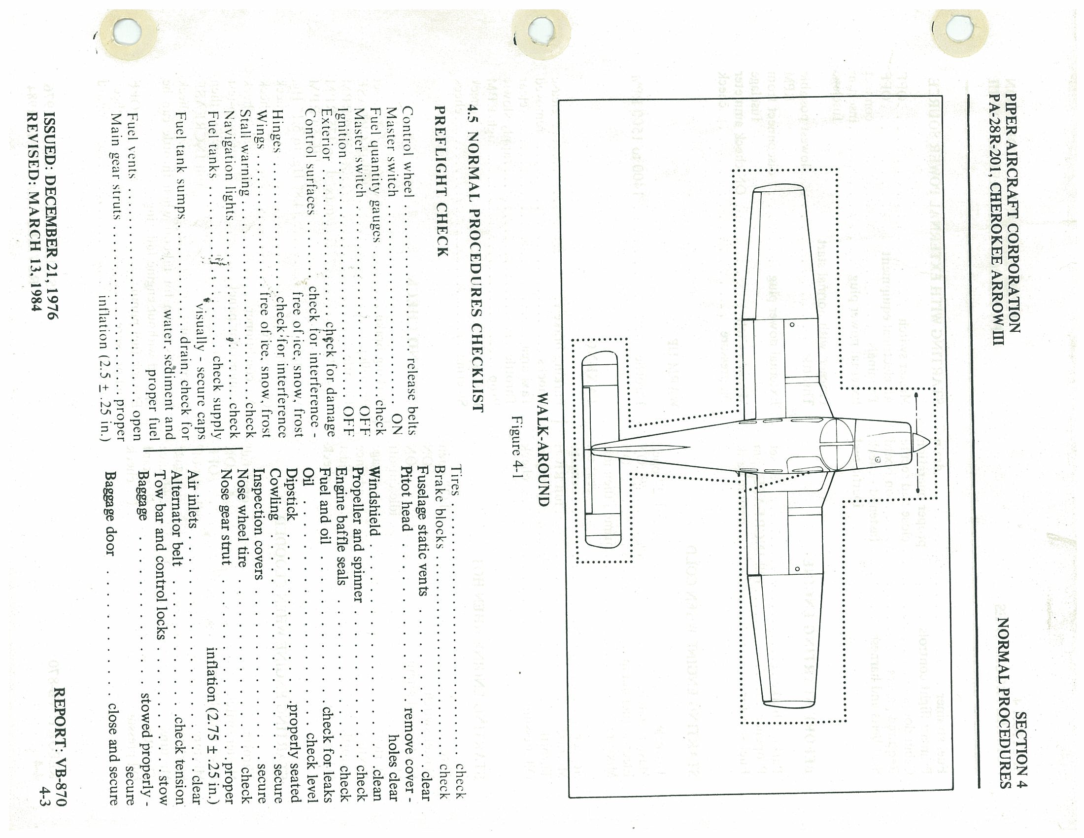
Preflight Check
- Control wheel — release belts
- Master switch — ON
- Fuel quantity gauges — check
- Master switch — OFF
- Ignition — OFF
- Exterior — check for damage
- Control surfaces — check for interference; free of ice, snow, frost
- Hinges — check for interference
- Wings — free of ice, snow, frost
- Stall warning — check
- Navigation lights — check
- Fuel tanks — check supply; visually secure caps
- Fuel tank sumps — drain, check for water, sediment and proper fuel
- Fuel vents — open
- Main gear struts — proper inflation (2.5 ± .25 in.)
- Tires — check
- Brake blocks — check
- Fuselage static vents — clear
- Pitot head — remove cover; holes clear
- Windshield — clean
- Propeller and spinner — check
- Engine baffle seals — check
- Fuel and oil — check for leaks
- Oil — check level
- Dipstick — properly seated
- Cowling — secure
- Inspection covers — secure
- Nose wheel tire — check
- Nose gear strut — proper inflation (2.75 ± .25 in.)
- Air inlets — clear
- Alternator belt — check tension
- Tow bar and control locks — stow
- Baggage — stowed properly; secure
- Baggage door — close and secure
Preflight Check (Continued) p. 55
- Fuel strainer — drain
- Primary flight controls — proper operation
- Cabin doors — close and secure
- Required papers — on board
- Seat belts and harness — fastened; check inertia reel
Before Starting Engine
- Parking brake — set
- Propeller — full INCREASE rpm
- Fuel selector — desired tank
Starting Engine When Cold
- Throttle — 1/2" open
- Master switch — ON
- Electric fuel pump — ON
- Mixture — prime, then idle cut-off
- Starter — engage
- Mixture — full RICH
- Throttle — adjust
- Oil pressure — check
Starting Engine When Hot
- Throttle — 1/2" open
- Master switch — ON
- Electric fuel pump — ON
- Mixture — idle cut-off
- Starter — engage
- Mixture — advance
- Throttle — adjust
- Oil pressure — check
Starting Engine When Flooded
- Throttle — open full
- Master switch — ON
- Electric fuel pump — OFF
- Mixture — idle cut-off
- Starter — engage
- Mixture — advance
- Throttle — retard
- Oil pressure — check
Starting With External Power Source
- Master switch — OFF
- All electrical equipment — OFF
- Terminals — connect
- External power plug — insert in fuselage
- Proceed with normal start
- Throttle — lowest possible RPM
- External power plug — disconnect from fuselage
- Master switch — ON; check ammeter
- Oil pressure — check
Warm-Up
- Throttle — 1400 to 1500 RPM
Taxiing
- Parking brake — release
- Chocks — removed
- Taxi area — clear
- Throttle — apply slowly
- Prop — high RPM
- Brakes — check
- Steering — check
Ground Check
- Parking brake — set
- Propeller — full INCREASE
- Throttle — 2000 RPM
- Magnetos — max. drop 175 RPM; max. diff. 50 RPM
- Vacuum — 4.8" Hg. to 5.1" Hg.
- Oil temp — check
- Oil pressure — check
- Air conditioner — check
- Annunciator panel — press-to-test
- Propeller — exercise, then full INCREASE
- Alternate air — check
- Engine is warm for takeoff when throttle can be opened without engine faltering.
- Electric fuel pump — OFF
- Fuel pressure — check
- Throttle — retard
Before Takeoff p. 56
- Master switch — ON
- Flight instruments — check
- Fuel selector — proper tank
- Electric fuel pump — ON
- Engine gauges — check
- Alternate air — CLOSED
- Seat backs — erect
- Mixture — set
- Prop — set
- Belts/harness — fastened
- Empty seats — seat belts snugly fastened
- Flaps — set
- Trim tab — set
- Controls — free
- Doors — latched
- Air conditioner — OFF
- Parking brake — released
Takeoff
Normal
- Flaps — set
- Tab — set
- Accelerate to 65 to 75 KIAS
- Control wheel — back pressure to rotate to climb attitude
Short Field, Obstacle Clearance
- Flaps — 25° (second notch)
- Accelerate to 50 to 60 KIAS depending on aircraft weight
- Control wheel — back pressure to rotate to climb attitude
- After breaking ground, accelerate to 55 to 65 KIAS depending on aircraft weight
- Gear (OVERRIDE ENGAGED on aircraft equipped with the backup gear extender) — UP
- Accelerate to best flaps up angle of climb speed — 78 KIAS; slowly retract the flaps and climb past the obstacle.
- Accelerate to best flaps up rate of climb speed — 90 KIAS
Soft Field
- Flaps — 25° (second notch)
- Accelerate to 50 to 60 KIAS depending on aircraft weight
- Control wheel — back pressure to rotate to climb attitude
- After breaking ground, accelerate to 55 to 65 KIAS depending on aircraft weight
- Gear (OVERRIDE ENGAGED on aircraft equipped with the backup gear extender) — UP
- Accelerate to best flaps up rate of climb speed — 90 KIAS
- Flaps — retract slowly
Climb
| Condition | Speed |
|---|---|
| Best rate (2750 lb) — gear up, flaps up | 90 KIAS |
| Best rate (2750 lb) — gear down, flaps up | 78 KIAS |
| Best angle (2750 lb) — gear up, flaps up | 78 KIAS |
| Best angle (2750 lb) — gear down, flaps up | 72 KIAS |
| En route | 104 KIAS |
- Electric fuel pump — OFF at desired altitude
Cruising
- Reference performance charts, Avco-Lycoming Operator's Manual and power setting table.
- Normal max power — 75%
- Power — set per power table
- Mixture — adjust
Approach and Landing p. 57
- Fuel selector — proper tank
- Seat backs — erect
- Belts/harness — fasten
- Electric fuel pump — ON
- Mixture — set
- Propeller — set
- Gear — down — 129 KIAS max
- Flaps — set — 103 KIAS max
- Air conditioner — OFF
- Trim to 75 KIAS
Stopping Engine
- Flaps — retract
- Electric fuel pump — OFF
- Air conditioner — OFF
- Radio's — OFF
- Propeller — full INCREASE
- Throttle — full aft
- Mixture — idle cut-off
- Magnetos — OFF
- Master switch — OFF
Parking
- Parking brake — set
- Control wheel — secured with belts
- Flaps — full up
- Wheel chocks — in place
- Tie downs — secure
4.7 Amplified Normal Procedures (General) p. 58
The following paragraphs are provided to supply detailed information and explanations of the normal procedures necessary for the safe operation of the airplane.
4.9 Preflight Check
The airplane should be given a thorough preflight and walk-around check. The preflight should include a check of the airplane's operational status, computation of weight and C.G. limits, takeoff distance and in-flight performance. A weather briefing should be obtained for the intended flight path, and any other factors relating to a safe flight should be checked before takeoff.
Upon entering the cockpit, release the seat belts securing the control wheel. Turn "ON" the master switch and check the fuel quantity gauges for sufficient fuel. After the fuel quantity check is made turn the master switch "OFF" and check that the ignition switch is "OFF."
To begin the exterior walk-around, check for external damage and operational interference of the control surfaces or hinges. Insure that the wings and control surfaces are free of snow, ice, frost or any other foreign materials.
An operational check of the stall warning system and exterior lights should now be made. Turn the master switch and appropriate light switches "ON." Lift the stall detector on the leading edge of the left wing while checking to determine that the warning horn is actuated, and check that navigation and anti-collision lights are illuminated. To check the optional heated pitot head, be sure to first remove any protective cover that might have been installed. With the heated pitot switch "ON" the pitot head should be found hot to touch. The master switch should be returned to the "OFF" position after these checks are complete.
A visual check of the fuel tank quantity should be performed. Remove the filler cap from each tank and visually check the supply and color. Be sure to secure the caps properly after the check is complete.
The fuel system tank sumps and strainer should be drained daily prior to the first flight and after refueling to avoid the accumulation of water or sediment. Each fuel tank is equipped with an individual quick drain located at the lower inboard rear corner of the tank. The fuel strainer is located on the left forward side of the fire wall.
Drain each tank through its individual quick drain located at the lower inboard rear corner of the tank, making sure that enough fuel has been drained to insure that all water and sediment is removed.
Check all of the fuel tank vents to make sure they are open.
Next, complete a check of the landing gear. Check the main gear shock struts for proper inflation. There should be 2.5 ± .25 inches of strut exposure under a normal static load. The nose gear should be checked for 2.75 ± .25 inches of strut exposure. Check all tires for cuts and wear and insure proper inflation. Make a visual check of the brake blocks for wear or damage.
Remove the cover from the pitot head on the underside of the left wing. Check the pitot head to make sure the holes are open and clear of obstructions. Check static vent holes on both sides of aft fuselage to make sure the holes are open and clear of obstructions.
Don't forget to clean and check the windshield.
The propeller and spinner should be checked for defects or nicks.
Lift the cowling and check for any obvious fuel or oil leaks. Check the oil level. Make sure that the dipstick has properly seated after checking. Secure the cowling and check the inspection covers.
Check the air inlets for foreign matter and the alternator belt for proper tension.
Stow the tow bar and check the baggage for proper storage and security. The baggage compartment doors should be closed and secure.
Upon entering the aircraft, ascertain that all primary flight controls operate properly. Close and secure the fore and aft cabin doors and check that all the required papers are in order and in the airplane.
Fasten the seat belts and shoulder harness and check the function of the inertia reel by pulling sharply on the strap. Fasten seat belts on empty seats.
4.11 Before Starting Engine
Before starting the engine the brakes should be set "ON" and the propeller lever moved to the full "INCREASE" rpm position. The fuel selector should then be moved to the desired tank.
4.13 Starting Engine p. 60
(a) Starting Engine When Cold
Open the throttle lever approximately 1/2 inch. Turn "ON" the master switch and the electric fuel pump. Move the mixture control to full "RICH" until an indication is noted on the fuel flow meter. The engine is now primed.
Move the mixture control to idle cut-off and engage the starter by rotating the magneto switch clockwise. When the engine fires, release the magneto switch, advance the mixture control to full "RICH" and move the throttle to the desired setting.
If the engine does not fire within five to ten seconds, disengage the starter and reprime.
(b) Starting Engine When Hot
Open the throttle approximately 1/2 inch. Turn "ON" the master switch and the electric fuel pump. Move the mixture control lever to idle cut-off and engage the starter by rotating the magneto switch clockwise. When the engine fires, release the magneto switch, advance the mixture and move the throttle to the desired setting.
(c) Starting Engine When Flooded
The throttle lever should be full "OPEN." Turn "ON" the master switch and turn "OFF" the emergency fuel pump. Move the mixture control lever to idle cut-off and engage the starter by rotating the magneto switch clockwise. When the engine fires, release the magneto switch, advance the mixture and retard the throttle.
(d) Starting Engine With External Power Source
An optional feature called the Piper External Power (PEP) allows the operator to use an external battery to crank the engine without having to gain access to the airplane's battery.
Turn the master switch OFF and turn all electrical equipment OFF. Connect the RED lead of the PEP kit jumper cable to the POSITIVE (+) terminal of an external 12-volt battery and the BLACK lead to the NEGATIVE (-) terminal. Insert the plug of the jumper cable into the socket located on the fuselage. Note that when the plug is inserted, the electrical system is ON. Proceed with the normal starting technique.
After the engine has started, reduce power to the lowest possible RPM, to reduce sparking, and disconnect the jumper cable from the aircraft. Turn the master switch ON and check the alternator ammeter for an indication of output. DO NOT ATTEMPT FLIGHT IF THERE IS NO INDICATION OF ALTERNATOR OUTPUT.
When the engine is firing evenly, advance the throttle to 800 RPM. If oil pressure is not indicated within thirty seconds, stop the engine and determine the trouble. In cold weather it will take a few seconds longer to get an oil pressure indication. If the engine has failed to start, refer to the Lycoming Operating Handbook, Engine Troubles and Their Remedies.
Starter manufacturers recommend that cranking periods be limited to thirty seconds with a two minute rest between cranking periods. Longer cranking periods will shorten the life of the starter.
4.15 Warm-Up p. 62
Warm-up the engine at 1400 to 1500 RPM. Avoid prolonged idling at low RPM, as this practice may result in fouled spark plugs.
Takeoff may be made as soon as the ground check is completed, provided that the throttle may be opened fully without backfiring or skipping, and without a reduction in engine oil pressure.
Do not operate the engine at high RPM when running up or taxiing over ground containing loose stones, gravel or any loose material that may cause damage to the propeller blades.
4.17 Taxiing
Before attempting to taxi the airplane, ground personnel should be instructed and approved by a qualified person authorized by the owner. Ascertain that the propeller back blast and taxi areas are clear.
After releasing the parking brake, power should be applied slowly to start the taxi roll. Taxi a few feet forward and apply the brakes to determine their effectiveness. Taxi with the propeller set in low pitch, high RPM setting. While taxiing, make slight turns to ascertain the effectiveness of the steering.
Observe wing clearances when taxiing near buildings or other stationary objects. If possible, station an observer outside the airplane.
Avoid holes and ruts when taxiing over uneven ground.
Do not operate the engine at high RPM when running up or taxiing over ground containing loose stones, gravel or any loose material that may cause damage to the propeller blades.
4.19 Ground Check
- Set the parking brake.
- Check magnetos at 2000 RPM with the propeller set at high RPM. Drop off on either magneto should not exceed 175 RPM and the difference between the magnetos should not exceed 50 RPM. Operation on one magneto should not exceed 10 seconds.
- Check the vacuum gauge; the indicator should read 4.8" Hg to 5.1" Hg at 2000 RPM.
- Check the annunciator panel lights with the press-to-test button. Also check the air conditioner and the alternate air.
- Release the parking brake.
4.21 Before Takeoff p. 63
All aspects of each particular takeoff should be considered prior to executing the takeoff procedure.
After all aspects of the takeoff are considered, a pretakeoff check procedure must be performed.
Turn "ON" the master switch and check and set all of the flight instruments as required. Check the fuel selector to make sure it is on the proper tank (fullest). Turn "ON" the electric fuel pump and check the engine gauges. The alternate air should be in the "CLOSED" position.
All seat backs should be erect.
The mixture and propeller control levers should be set and the seat belts and shoulder harness fastened. Fasten the seat belts snugly around the empty seats.
Exercise and set the flaps and trim tab. Ensure proper flight control movement and response.
All doors should be properly secured and latched.
On air conditioned models, the air conditioner must be "OFF" to ensure normal takeoff performance.
*Approximately 75 KIAS at sea level to approximately 88 KIAS at 10,000 ft with a straight line variation between.
4.23 Takeoff p. 64
The normal takeoff technique is conventional for the Cherokee Arrow III. The tab should be set slightly aft of neutral, with the exact setting determined by the loading of the airplane. Allow the airplane to accelerate to 65 to 75 KIAS depending on the weight of the aircraft and ease back on the control wheel to rotate to climb attitude.
The procedure used for a short field takeoff with an obstacle or a soft field takeoff differs slightly from the normal technique. The flaps should be lowered to 25° (second notch). Allow the aircraft to accelerate to 50 to 60 KIAS depending on the aircraft weight and rotate the aircraft to climb attitude. After breaking ground, accelerate to 55 to 65 KIAS, depending on aircraft weight and select gear up*. Continue to climb while accelerating to the flaps up rate of climb speed, 90 KIAS if no obstacle is present or to the best flaps up angle of climb speed, 78 KIAS if obstacle clearance is a consideration. Retract the flaps slowly, one notch at a time, while climbing out.
*If desired, on aircraft equipped with the backup gear extender the "OVERRIDE ENGAGED" position can be selected and locked before takeoff, and the gear will then retract as soon as the gear selector switch is placed in the up position. In this case care should be taken not to retract the gear prematurely, or the aircraft could settle back onto the runway. If the override lock is used for takeoff, it should be disengaged as soon as sufficient terrain clearance is obtained, to return the gear system to normal operation.
4.25 Climb
The best rate of climb at gross weight will be obtained at 90 KIAS. The best angle of climb may be obtained at 78 KIAS. At lighter than gross weight these speeds are reduced somewhat**. For climbing en route, a speed of 104 KIAS is recommended. This will produce better forward speed and increased visibility over the nose during the climb.
When reaching the desired altitude, the electric fuel pump may be turned off.
**To obtain the performance presented in the Performance Section of this handbook, full power (full throttle and 2700 RPM) must be used.
4.27 Cruising p. 65
The cruising speed of the Cherokee Arrow III is determined by many factors, including power setting, altitude, temperature, loading and equipment installed in the airplane.
The normal maximum cruising power is 75% of the rated horsepower of the engine. When selecting cruising RPM below 2400, limiting manifold pressure for continuous operation, as specified by the appropriate "Avco-Lycoming Operator's Manual," should be observed.
To obtain the desired power, set the manifold pressure and RPM according to the power setting table in this manual.
Use of the mixture control in cruising flight reduces fuel consumption significantly, especially at higher altitudes. The mixture should be leaned during cruising operation when 75% power or less is being used. If any doubt exists as to the amount of power being used, the mixture should be in the full "RICH" position for all operations.
To lean the mixture, disengage the lock and pull the mixture control until the engine becomes rough, indicating that the lean mixture limit has been reached in the leaner cylinders. Then enrich the mixture by pushing the control towards the instrument panel until engine operation becomes smooth. The fuel flow meter will give a close approximation of the fuel being consumed. The low side of the power setting, as shown on the fuel flow meter, indicates best economy for that percent of power while the high side indicates best power.
If the airplane is equipped with the optional exhaust gas temperature (EGT) gauge, a more accurate means of leaning is available to the pilot. For this procedure, refer to the "Avco-Lycoming Operator's Manual."
In order to keep the airplane in best lateral trim during cruise flight, the fuel should be used alternately from each tank at one hour intervals.
4.29 Approach and Landing p. 66
Check to insure the fuel selector is on the proper (fullest) tank and that the seat backs are erect. The seat belts and shoulder harness should be fastened and the inertia reel checked.
Turn "ON" the electric fuel pump and turn "OFF" the air conditioner. The mixture should be set in the full "RICH" position. Set the propeller at full "INCREASE" rpm to facilitate ample power for an emergency go-around.
The landing gear may be extended at speeds below 129 KIAS. The airplane should be trimmed to a final approach speed of about 75 KIAS with flaps extended. The flaps can be lowered at speeds up to 103 KIAS, if desired.
The mixture control should be kept in full "RICH" position to insure maximum acceleration if it should be necessary to open the throttle again.
The amount of flap used during landings and the speed of the aircraft at contact with the runway should be varied according to the landing surface and conditions of wind and airplane loading. It is generally good practice to contact the ground at the minimum possible safe speed consistent with existing conditions.
Normally, the best technique for short and slow landings is to use full flap and enough power to maintain the desired airspeed and approach flight path. Mixture should be full "RICH," fuel on the fullest tank, and electric fuel pump "ON." Reduce the speed during the flareout and contact the ground close to the stalling speed. After ground contact hold the nose wheel off as long as possible. As the airplane slows down, gently lower the nose and apply the brakes. Braking is most effective when flaps are raised and back pressure is applied to the control wheel, putting most of the aircraft weight on the main wheels. In high wind conditions, particularly in strong crosswinds, it may be desirable to approach the ground at higher than normal speeds with partial or no flaps.
4.31 Stopping Engine
At the pilot's discretion, the flaps should be raised and the electric fuel pump turned "OFF."
The air conditioner and radios should be turned "OFF," the propeller set in the full "INCREASE" position, and the engine stopped by disengaging the mixture control lock and pulling the mixture control back to idle cut-off. The throttle should be left full aft to avoid engine vibration while stopping. Then the magneto and master switches must be turned "OFF."
4.33 Parking p. 67
If necessary, the airplane should be moved on the ground with the aid of the nose wheel tow bar provided with each airplane and secured behind the rear seats. The aileron and stabilator controls should be secured by looping the safety belt through the control wheel and pulling it snug. The flaps are locked when in the "UP" position and should be left retracted.
Tie downs can be secured to rings provided under each wing and to the tail skid. The rudder is held in position by its connections to the nose wheel steering and normally does not have to be secured.
4.35 Stalls
The stall characteristics of the Cherokee Arrow III are conventional. An approaching stall is indicated by a stall warning horn which is activated between five and ten knots above stall speed. Mild airframe buffeting and gentle pitching may also precede the stall.
The gross weight stalling speed of the Cherokee Arrow III with power off and full flaps is 55 KIAS. With the flaps up this speed is increased 5 KTS. Loss of altitude during stalls can be as great as 400 feet, depending on configuration and power.
During preflight, the stall warning system should be checked by turning the master switch "ON," lifting the detector and checking to determine if the horn is actuated. The master switch should be returned to the "OFF" position after the check is complete.
4.37 Turbulent Air Operation
In keeping with good operating practice used in all aircraft, it is recommended that when turbulent air is encountered or expected, the airspeed be reduced to maneuvering speed to reduce the structural loads caused by gusts and to allow for inadvertent speed build-ups which may occur as a result of the turbulence or of distractions caused by the conditions.
4.39 Landing Gear p. 68
Some airplanes are equipped with an airspeed-power sensing system (backup gear extender) which extends the landing gear under low airspeed-power conditions* even though the pilot may not have selected gear down. This system will also prevent retraction of the landing gear by normal means when the airspeed-power values are below a predetermined minimum. To override this system or to hold the emergency gear lever in the "OVERRIDE ENGAGED" position without maintaining manual pressure on the emergency gear lever, pull the lever full up and push the lock pin in. To release the override, pull lever up and then release. For normal operation, the pilot should extend and retract the gear with the gear selector switch located on the instrument panel, just as he would if the backup gear extender system were not installed.
The pilot should become familiar with the function and significance of the landing gear position indicators and warning lights.
The red gear warning light on the instrument panel and the horn operate simultaneously in flight when the throttle is reduced to where the manifold pressure is approximately 14 inches of mercury or below, and the gear selector switch is not in the "DOWN" position. On aircraft equipped with the backup gear extender, this warning will also occur during flight when the system has lowered the landing gear and the gear selector switch is not in the "DOWN" position and the manifold pressure is reduced below approximately 14 inches of mercury.
The red gear warning light on the instrument panel and the horn will also operate simultaneously on the ground when the master switch is "ON" and the gear selector switch is in the "UP" position and the throttle is in the retarded position.
The three green lights on the instrument panel operate individually as each associated gear is locked in the extended position.
On aircraft equipped with the backup gear extender, the yellow "Auto Ext. OFF" light immediately below the gear selector switch flashes whenever the emergency gear lever is in the "OVERRIDE ENGAGED" position.
When the Emergency Landing Gear Extension Procedure (paragraph 3.27) is performed for training purposes, the following changes must be made to the procedure in order to prevent the hydraulic pump from activating during the procedure. On aircraft equipped with the backup gear extender, the landing gear selector must be left in the UP position until all gear position indicators are green. On aircraft which do NOT have the backup gear extender, a pull type LANDING GEAR PUMP circuit breaker is installed and must be pulled prior to executing the emergency extension procedure. The circuit breaker must be reset after completion of the procedure to allow normal system operation.
4.41 Weight and Balance
It is the responsibility of the owner and pilot to determine that the airplane remains within the allowable weight vs. center of gravity envelope while in flight.
For weight and balance data, refer to section 6 (Weight and Balance).
*Approximately 95 KIAS at any altitude, power off.
Section 5 — Performance p. 70
| Paragraph No. | Title | Page No. |
|---|---|---|
| 5.1 | General | 5-1 |
| 5.3 | Introduction to Performance and Flight Planning | 5-1 |
| 5.5 | Flight Planning Example | 5-3 |
| 5.7 | Performance Graphs | 5-9 |
| List of Figures | 5-9 |
5.1 General p. 71
All of the required (FAA regulations) and complementary performance information applicable to the Cherokee Arrow III is provided by this section.
Performance information associated with those optional systems and equipment which require handbook supplements is provided by Section 9 (Supplements).
5.3 Introduction to Performance and Flight Planning
The performance information presented in this section is based on measured Flight Test Data corrected to I.C.A.O. standard day conditions and analytically expanded for the various parameters of weight, altitude, temperature, etc.
The performance charts are unfactored and do not make any allowance for varying degrees of pilot proficiency or mechanical deterioration of the aircraft. This performance, however, can be duplicated by following the stated procedures in a properly maintained airplane.
Effects of conditions not considered on the charts must be evaluated by the pilot, such as the effect of soft or grass runway surface on takeoff and landing performance, or the effect of winds aloft on cruise and range performance. Endurance can be grossly affected by improper leaning procedures, and inflight fuel flow and quantity checks are recommended.
The information provided by paragraph 5.5 (Flight Planning Example) outlines a detailed flight plan using the performance charts in this section. Each chart includes its own example to show how it is used.
5.5 Flight Planning Example p. 73
(a) Aircraft Loading
The first step in planning our flight is to calculate the airplane weight and center of gravity by utilizing the information provided by Section 6 (Weight and Balance) of this handbook.
The basic empty weight for the airplane as delivered from the factory has been entered in Figure 6-5. If any alterations to the airplane have been made effecting weight and balance, reference to the aircraft logbook and Weight and Balance Record (Figure 6-7) should be made to determine the current basic empty weight of the airplane.
Make use of the Weight and Balance Loading Form (Figure 6-11) and the C.G. Range and Weight graph (Figure 6-15) to determine the total weight of the airplane and the center of gravity position.
After proper utilization of the information provided we have found the following weights for consideration in our flight planning example.
The landing weight cannot be determined until the weight of the fuel to be used has been established — refer to item (g)(1).
| # | Item | Weight |
|---|---|---|
| (1) | Basic Empty Weight | 1890 lbs. |
| (2) | Occupants (2 × 170 lbs.) | 340 lbs. |
| (3) | Baggage and Cargo | 70 lbs. |
| (4) | Fuel (6 lb. × 50 gal.) | 300 lbs. |
| (5) | Takeoff Weight | 2600 lbs. |
| (6) | Landing Weight — (a)(5) minus (g)(1), (2600 lbs. minus 62 lbs.) | 2538 lbs. |
Our takeoff weight is below the maximum of 2750 lbs. and our weight and balance calculations have determined our C.G. position within the approved limits.
(b) Takeoff and Landing
Now that we have determined our aircraft loading, we must consider all aspects of our takeoff and landing.
All of the existing conditions at the departure and destination airport must be acquired, evaluated and maintained throughout the flight.
Apply the departure airport conditions and takeoff weight to the appropriate Takeoff Performance and Takeoff Ground Roll graph (Figures 5-5, 5-7, 5-9 and 5-11) to determine the length of runway necessary for the takeoff and/or the barrier distance.
The landing distance calculations are performed in the same manner using the existing conditions at the destination airport and, when established, the landing weight.
p. 74 The conditions and calculations for our example flight are listed below. The takeoff and landing distances required for our example flight have fallen well below the available runway lengths.
| # | Item | Departure Airport | Destination Airport |
|---|---|---|---|
| (1) | Pressure Altitude | 1900 ft. | 1900 ft. |
| (2) | Temperature | 20°C | 20°C |
| (3) | Wind Component | 4 KTS (Headwind) | 2 KTS (Headwind) |
| (4) | Runway Length Available | 3000 ft. | 4600 ft. |
| (5) | Runway Required | 2550 ft.* | 1490 ft.** |
(c) Climb
The next step in our flight plan is to determine the necessary climb segment components.
The desired cruise pressure altitude and corresponding cruise outside air temperature values are the first variables to be considered in determining the climb components from the Fuel, Time and Distance to Climb graph (Figure 5-17). After the fuel, time and distance for the cruise pressure altitude and outside air temperature values have been established, apply the existing conditions at the departure field to the graph (Figure 5-17). Now, subtract the values obtained from the graph for the field of departure conditions from those for the cruise pressure altitude.
The remaining values are the true fuel, time and distance components for the climb segment of the flight plan corrected for field pressure altitude and temperature.
The following values were determined from the above instructions in our flight planning example.
| # | Item | Value |
|---|---|---|
| (1) | Cruise Pressure Altitude | 6000 ft. |
| (2) | Cruise OAT | 10°C |
| (3) | Fuel to Climb (2 gal. minus 1 gal.) | 2 gal.*** |
| (4) | Time to Climb (10 min. minus 3.5 min.) | 6.5 min.*** |
| (5) | Distance to Climb (17 nautical miles minus 6 nautical miles) | 11 nautical miles*** |
* reference Figure 5-9
** reference Figure 5-35
*** reference Figure 5-17
(d) Descent p. 75
The descent data will be determined prior to the cruise data to provide the descent distance for establishing the total cruise distance.
Utilizing the cruise pressure altitude and OAT we determine the basic fuel, time and distance for descent (Figure 5-31). These figures must be adjusted for the field pressure altitude and temperature at the destination airport. To find the necessary adjustment values, use the existing pressure altitude and temperature conditions at the destination airport as variables to find the fuel, time and distance values from the graph (Figure 5-31). Now, subtract the values obtained from the field conditions from the values obtained from the cruise conditions to find the true fuel, time and distance values needed for the flight plan.
The values obtained by proper utilization of the graphs for the descent segment of our example are shown below.
| # | Item | Calculation | Result |
|---|---|---|---|
| (1) | Fuel to Descend | 1.0 gal. minus 0.5 gal. | 0.5 gal.* |
| (2) | Time to Descend | 7 min. minus 3 min. | 4 min.* |
| (3) | Distance to Descend | 18 nautical miles minus 8 nautical miles | 10 nautical miles* |
*reference Figure 5-31
(e) Cruise
Using the total distance to be traveled during the flight, subtract the previously calculated distance to climb and distance to descend to establish the total cruise distance. Refer to the appropriate Avco Lycoming Operator's Manual and the Power Setting Table (Figure 5-19) when selecting the cruise power setting. The established pressure altitude and temperature values and the selected cruise power should now be utilized to determine the true airspeed from the appropriate Speed Power graph (Figure 5-21 or 5-23).
Calculate the cruise fuel flow for the cruise power setting from the information provided by the Avco Lycoming Operator's Manual.
The cruise time is found by dividing the cruise distance by the cruise speed and the cruise fuel is found by multiplying the cruise fuel flow by the cruise time.
The cruise calculations established for the cruise segment of our flight planning example are as follows:
| # | Item | Calculation | Result |
|---|---|---|---|
| (1) | Total Distance | — | 130 nautical miles |
| (2) | Cruise Distance | (e)(1) minus (c)(4) minus (d)(2) 130 nm minus 11 nm minus 10 nm |
109 nautical miles |
| (3) | Cruise Power (Economy cruise) | — | 65% rated power |
| (4) | Cruise Speed | — | 129 KTS TAS** |
| (5) | Cruise Fuel Consumption | — | 9.2 GPH |
| (6) | Cruise Time | (e)(2) divided by (e)(4) 109 nautical miles divided by 129 KTS |
.85 hrs. (51 min.) |
| (7) | Cruise Fuel | (e)(5) multiplied by (e)(6) 9.2 GPH multiplied by .85 hrs. |
7.8 gal. |
**reference Figure 5-21
(f) Total Flight Time p. 76
The total flight time is determined by adding the time to climb, the time to descend and the cruise time. Remember! The time values taken from the climb and descent graphs are in minutes and must be converted to hours before adding them to the cruise time.
The following flight time is required for our flight planning example:
| # | Item | Calculation | Result |
|---|---|---|---|
| (1) | Total Flight Time | (c)(3) plus (d)(1) plus (e)(6) .11 hrs. plus .07 hrs. plus .85 hrs. (6.5 min. plus 4 min. plus 51 min.) |
1.03 hrs. 61.5 min. |
(g) Total Fuel Required
Determine the total fuel required by adding the fuel to climb, the fuel to descend and the cruise fuel. When the total fuel (in gallons) is determined, multiply this value by 6 lb/gal to determine the total fuel weight used for the flight.
The total fuel calculations for our example flight plan are shown below:
| # | Item | Calculation | Result |
|---|---|---|---|
| (1) | Total Fuel Required | (c)(5) plus (d)(3) plus (e)(7) 2 gal. plus 0.5 gal. plus 7.8 gal. (10.3 gal. multiplied by 6 lb/gal.) |
10.3 gal. 62 lbs. |
— Page 77 intentionally left blank —
5.7 Performance Graphs p. 79
List of Figures
| Figure No. | Title | Page No. |
|---|---|---|
| 5-1 | Airspeed System Calibration | 5-11 |
| 5-3 | Power Off Stall Speed Versus Angle of Bank | 5-12 |
| 5-5 | 25° Flap Takeoff Performance Over 50 Foot Barrier | 5-13 |
| 5-7 | 25° Flap Takeoff Ground Roll | 5-14 |
| 5-9 | 0° Flap Takeoff Performance Over 50 Foot Barrier | 5-15 |
| 5-11 | 0° Flap Takeoff Ground Roll | 5-16 |
| 5-13 | Gear Up Climb Performance | 5-17 |
| 5-15 | Gear Down Climb Performance | 5-18 |
| 5-17 | Fuel, Time and Distance to Climb | 5-19 |
| 5-19 | Power Setting Table | 5-21 |
| 5-21 | Speed Power - Performance Cruise | 5-23 |
| 5-23 | Speed Power - Economy Cruise | 5-24 |
| 5-25 | Range - Best Power | 5-25 |
| 5-27 | Range - Best Economy | 5-26 |
| 5-29 | Endurance | 5-27 |
| 5-31 | Fuel, Time and Distance to Descend | 5-28 |
| 5-33 | Glide Time and Distance | 5-29 |
| 5-35 | Landing Distance Over 50 Foot Barrier | 5-30 |
| 5-37 | Landing Ground Roll Distance | 5-31 |
Airspeed Calibration p. 81
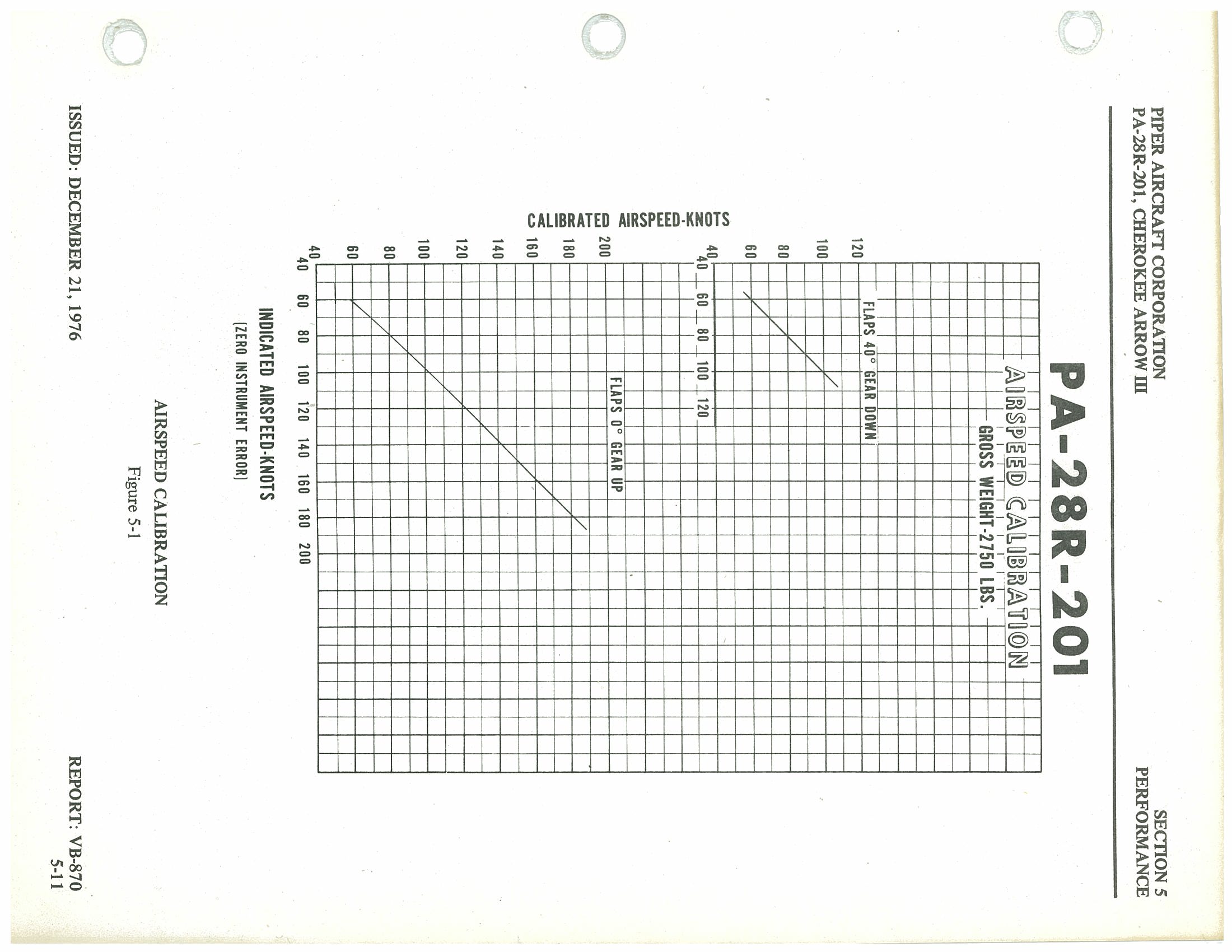
| Indicated Airspeed (KIAS) | Calibrated Airspeed — Flaps 0° Gear Up (KCAS) | Calibrated Airspeed — Flaps 40° Gear Down (KCAS) |
|---|---|---|
| 40 | 40 | 40 |
| 60 | 60 | 60 |
| 80 | 80 | 80 |
| 100 | 100 | 100 |
| 120 | 120 | 120 |
| 140 | 140 | — |
| 160 | 160 | — |
| 180 | 180 | — |
| 200 | 200 | — |
Power Off Stall Speed Versus Angle of Bank p. 82
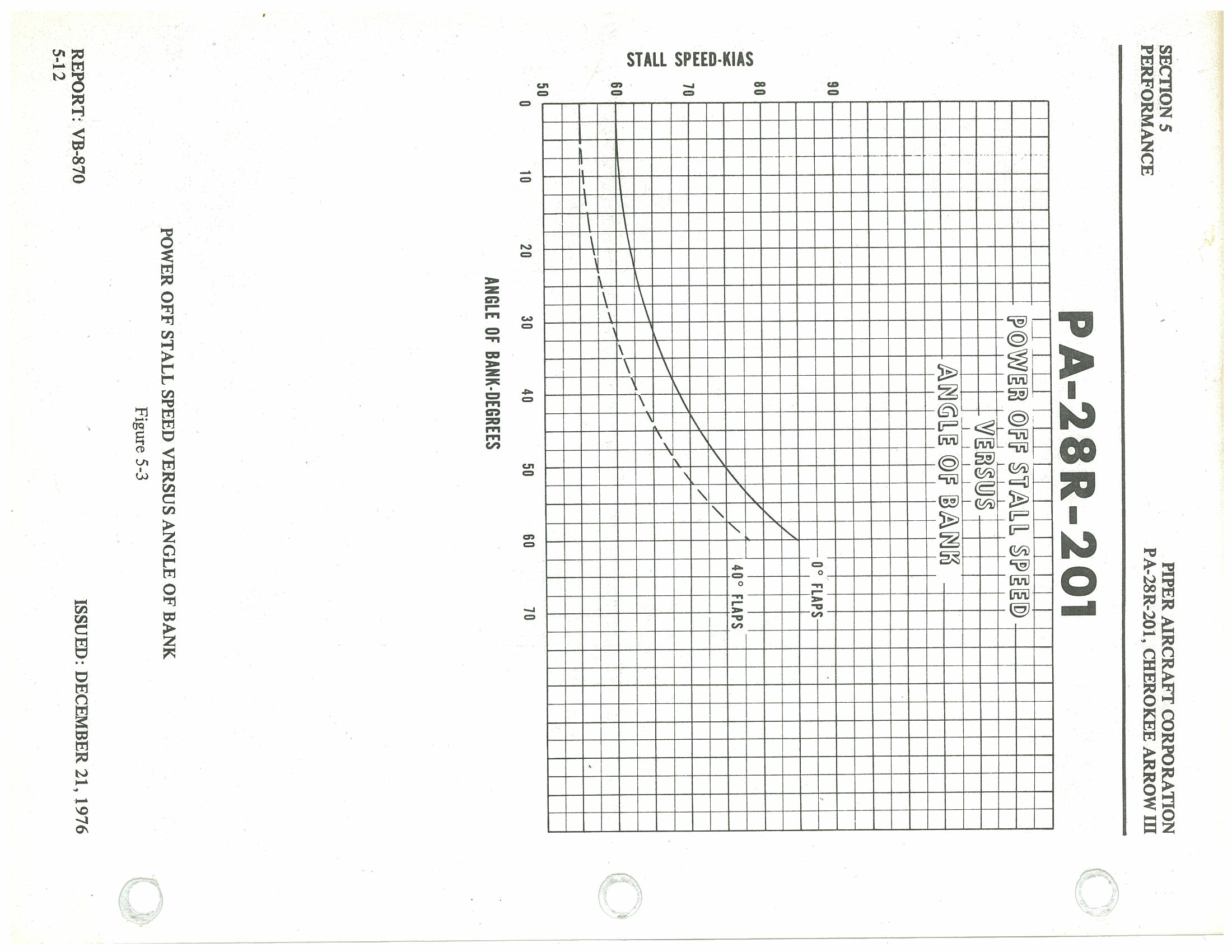
| Angle of Bank (degrees) | Stall Speed — Flaps 0° (KIAS) | Stall Speed — Flaps 40° (KIAS) |
|---|---|---|
| 0 | 55 | 53 |
| 10 | 56 | 54 |
| 20 | 57 | 55 |
| 30 | 60 | 57 |
| 40 | 64 | 61 |
| 45 | 66 | 63 |
| 50 | 70 | 66 |
| 60 | 78 | 74 |
| 70 | 90 | 76 |
25° Flap Takeoff Performance Over 50 Foot Barrier p. 83
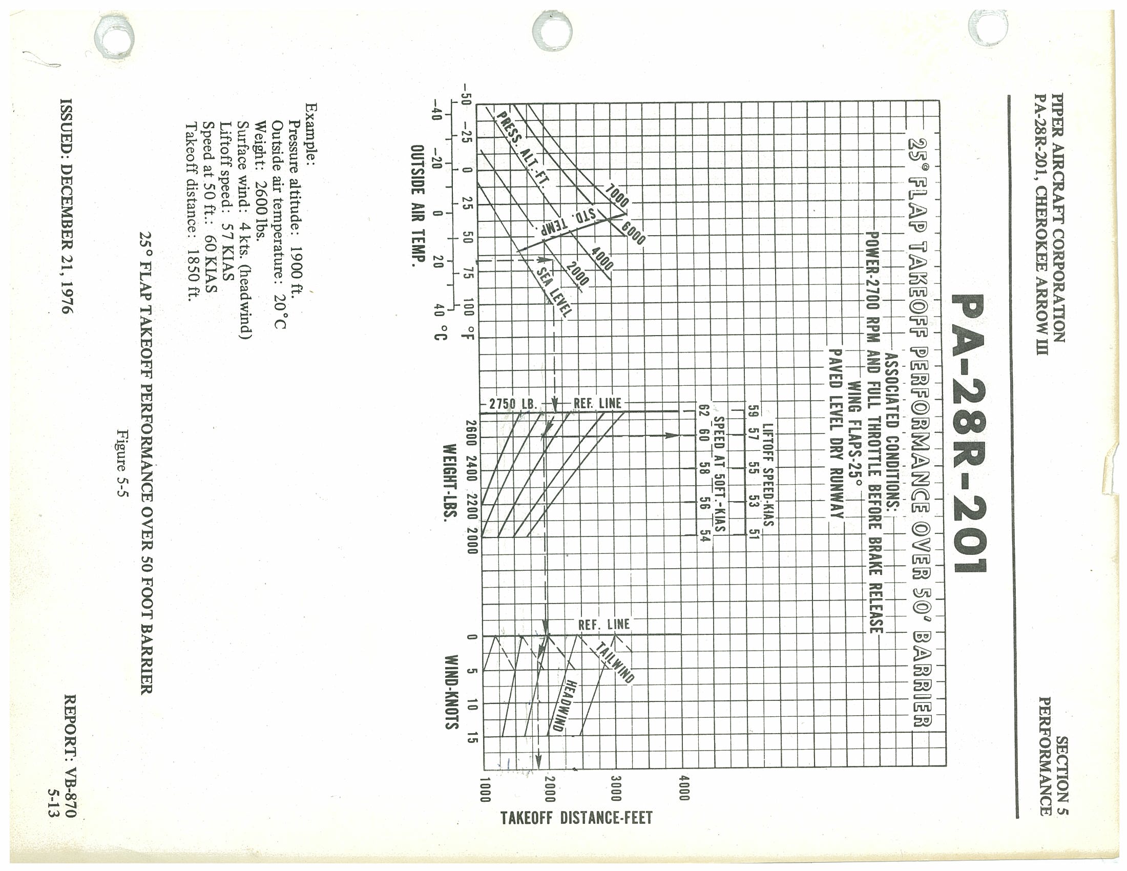
Associated Conditions
- Power: 2700 RPM and full throttle before brake release
- Wing Flaps: 25°
- Runway: Paved, level, dry
| Gross Weight (lbs) | Liftoff Speed (KIAS) | Speed at 50 ft (KIAS) |
|---|---|---|
| 2750 | 59 | 62 |
| 2600 | 57 | 60 |
| 2400 | 55 | 58 |
| 2200 | 53 | 56 |
| 2000 | 51 | 54 |
Worked Example
- Pressure altitude: 1900 ft
- Outside air temperature: 20°C
- Weight: 2600 lbs
- Surface wind: 4 kts (headwind)
- Liftoff speed: 57 KIAS
- Speed at 50 ft: 60 KIAS
- Takeoff distance: 1850 ft
25° Flap Takeoff Ground Roll p. 84
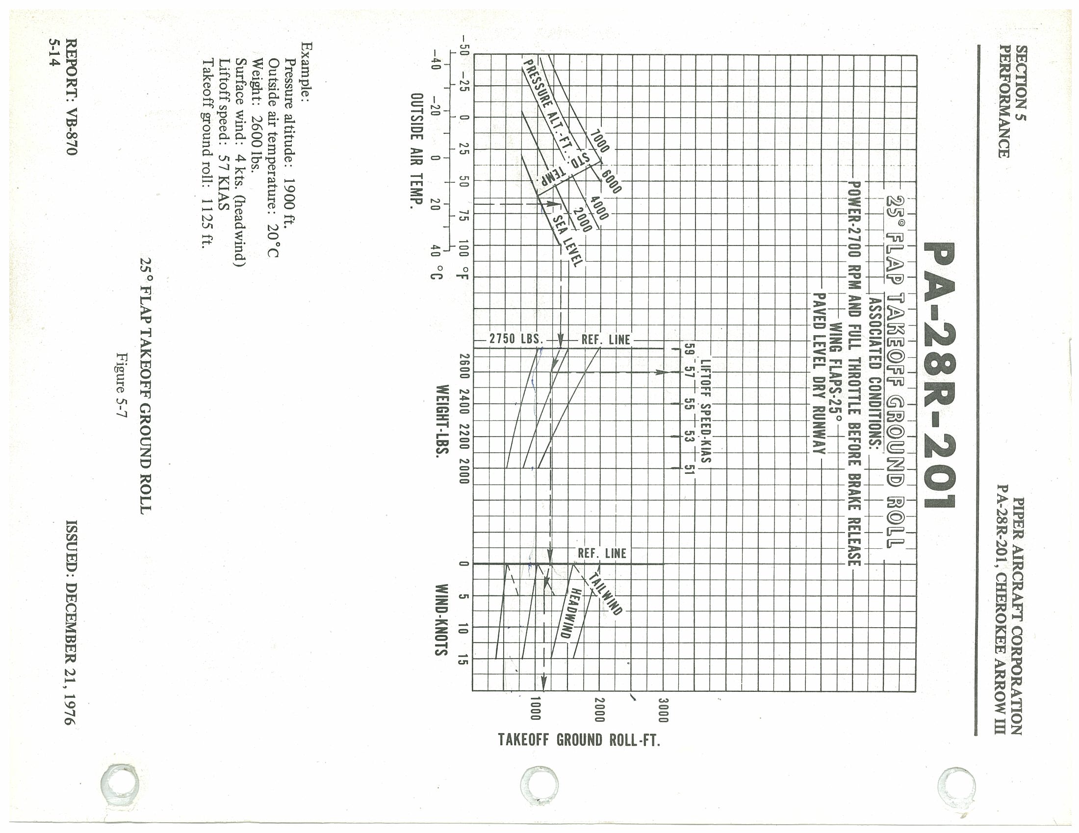
Associated Conditions:
- Power: 2700 RPM and full throttle before brake release
- Wing flaps: 25°
- Paved level dry runway
Liftoff Speeds — 25° Flaps
| Weight (lbs) | Liftoff Speed (KIAS) |
|---|---|
| 2750 | 59 |
| 2600 | 57 |
| 2400 | 55 |
| 2200 | 53 |
| 2000 | 51 |
Example
| Pressure altitude | 1900 ft. |
| Outside air temperature | 20°C |
| Weight | 2600 lbs. |
| Surface wind | 4 kts. (headwind) |
| Liftoff speed | 57 KIAS |
| Takeoff ground roll | 1125 ft. |
0° Flap Takeoff Distance Over 50 Foot Barrier p. 85
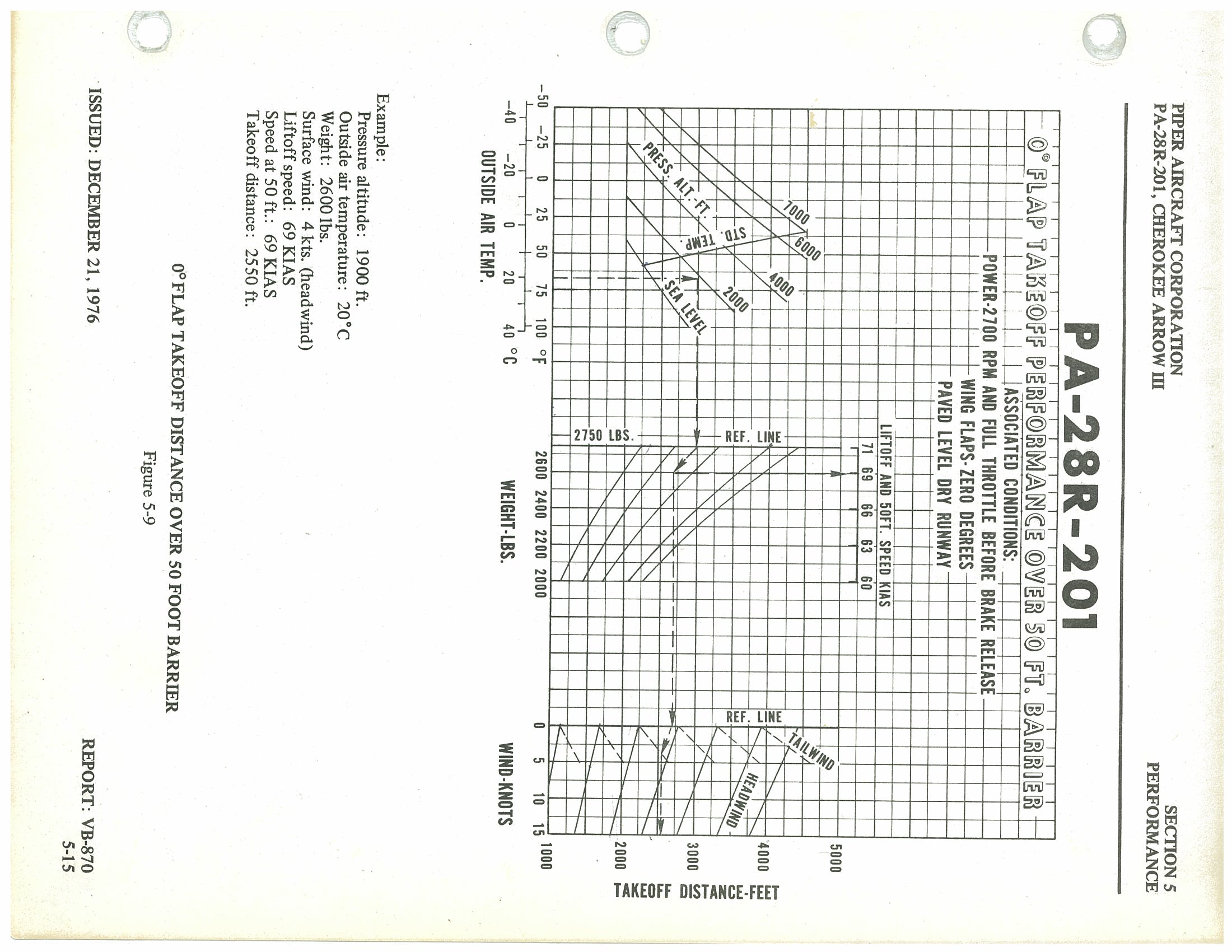
Associated Conditions:
- Power: 2700 RPM and full throttle before brake release
- Wing flaps: zero degrees
- Paved level dry runway
Liftoff and 50 ft. Speeds — 0° Flaps
| Weight (lbs) | Liftoff & 50 ft. Speed (KIAS) |
|---|---|
| 2750 | 71 |
| 2600 | 69 |
| 2400 | 66 |
| 2200 | 63 |
| 2000 | 60 |
Example
| Pressure altitude | 1900 ft. |
| Outside air temperature | 20°C |
| Weight | 2600 lbs. |
| Surface wind | 4 kts. (headwind) |
| Liftoff speed | 69 KIAS |
| Speed at 50 ft. | 69 KIAS |
| Takeoff distance | 2550 ft. |
0° Flap Takeoff Ground Roll p. 86
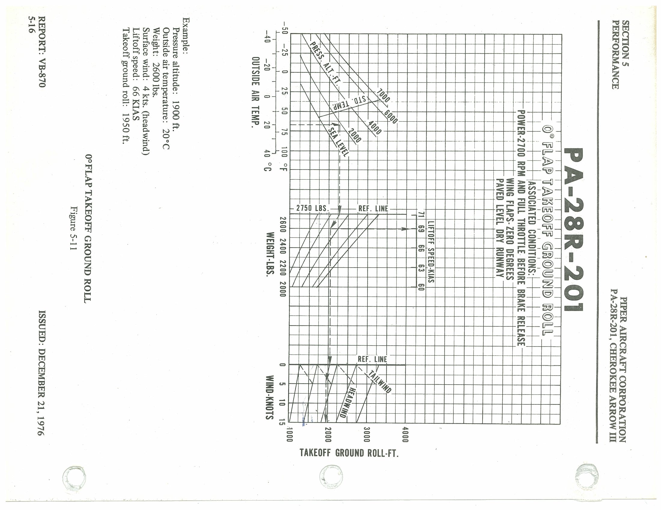
Associated Conditions:
- Power: 2700 RPM and full throttle before brake release
- Wing flaps: zero degrees
- Paved level dry runway
Liftoff Speeds — 0° Flaps
| Weight (lbs) | Liftoff Speed (KIAS) |
|---|---|
| 2750 | 71 |
| 2600 | 69 |
| 2400 | 66 |
| 2200 | 63 |
| 2000 | 60 |
Example
| Pressure altitude | 1900 ft. |
| Outside air temperature | 20°C |
| Weight | 2600 lbs. |
| Surface wind | 4 kts. (headwind) |
| Liftoff speed | 66 KIAS |
| Takeoff ground roll | 1950 ft. |
Gear Up Climb Performance p. 87
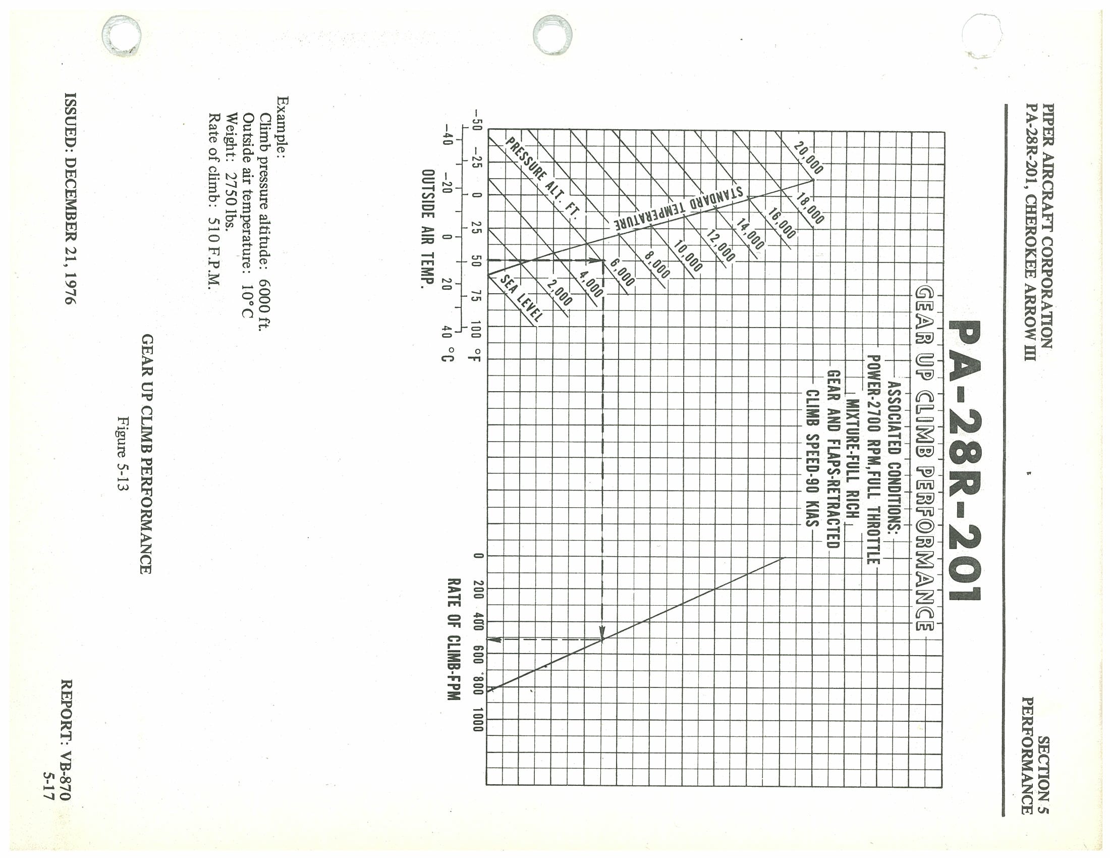
Associated Conditions:
- Power: 2700 RPM, Full Throttle
- Mixture: Full Rich
- Gear and Flaps: Retracted
- Climb Speed: 90 KIAS
| Parameter | Value |
|---|---|
| Climb Pressure Altitude | 6,000 ft |
| Outside Air Temperature | 10°C |
| Weight | 2,750 lbs |
| Rate of Climb | 510 F.P.M. |
Gear Down Climb Performance p. 88
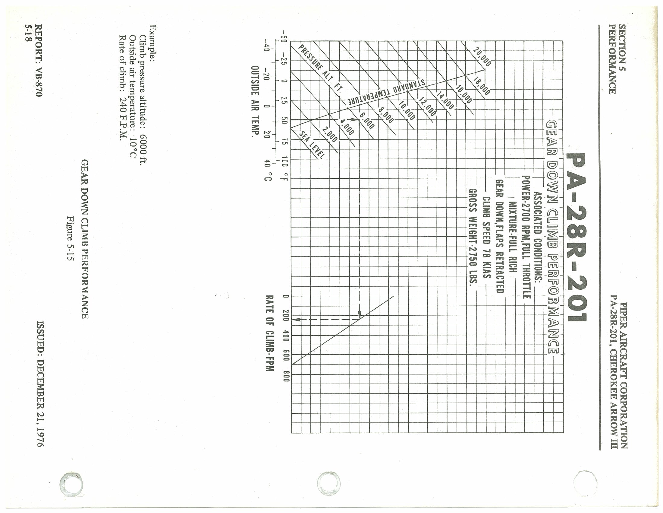
Associated Conditions:
- Power: 2700 RPM, Full Throttle
- Mixture: Full Rich
- Gear Down, Flaps Retracted
- Climb Speed: 78 KIAS
- Gross Weight: 2,750 lbs
| Parameter | Value |
|---|---|
| Climb Pressure Altitude | 6,000 ft |
| Outside Air Temperature | 10°C |
| Rate of Climb | 240 F.P.M. |
Fuel, Time and Distance to Climb p. 89
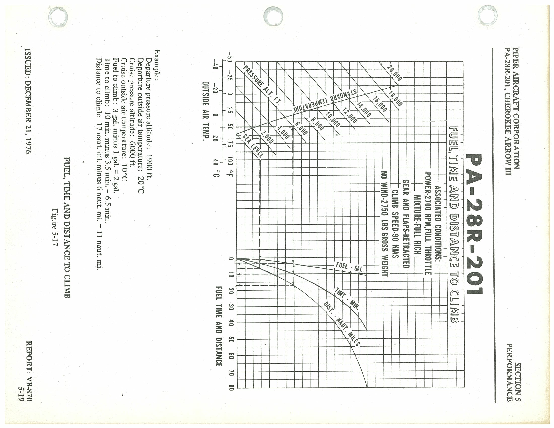
Associated Conditions:
- Power: 2700 RPM, Full Throttle
- Mixture: Full Rich
- Gear and Flaps: Retracted
- Climb Speed: 90 KIAS
- No Wind
- Gross Weight: 2,750 lbs
| Parameter | Departure (1,900 ft / 20°C) | Cruise (6,000 ft / 10°C) | Net (Climb Segment) |
|---|---|---|---|
| Fuel to Climb | 1 gal | 3 gal | 2 gal |
| Time to Climb | 3.5 min | 10 min | 6.5 min |
| Distance to Climb | 6 naut. mi. | 17 naut. mi. | 11 naut. mi. |
Power Setting Table — Lycoming Model IO-360-C Series, 200 HP Engine p. 91
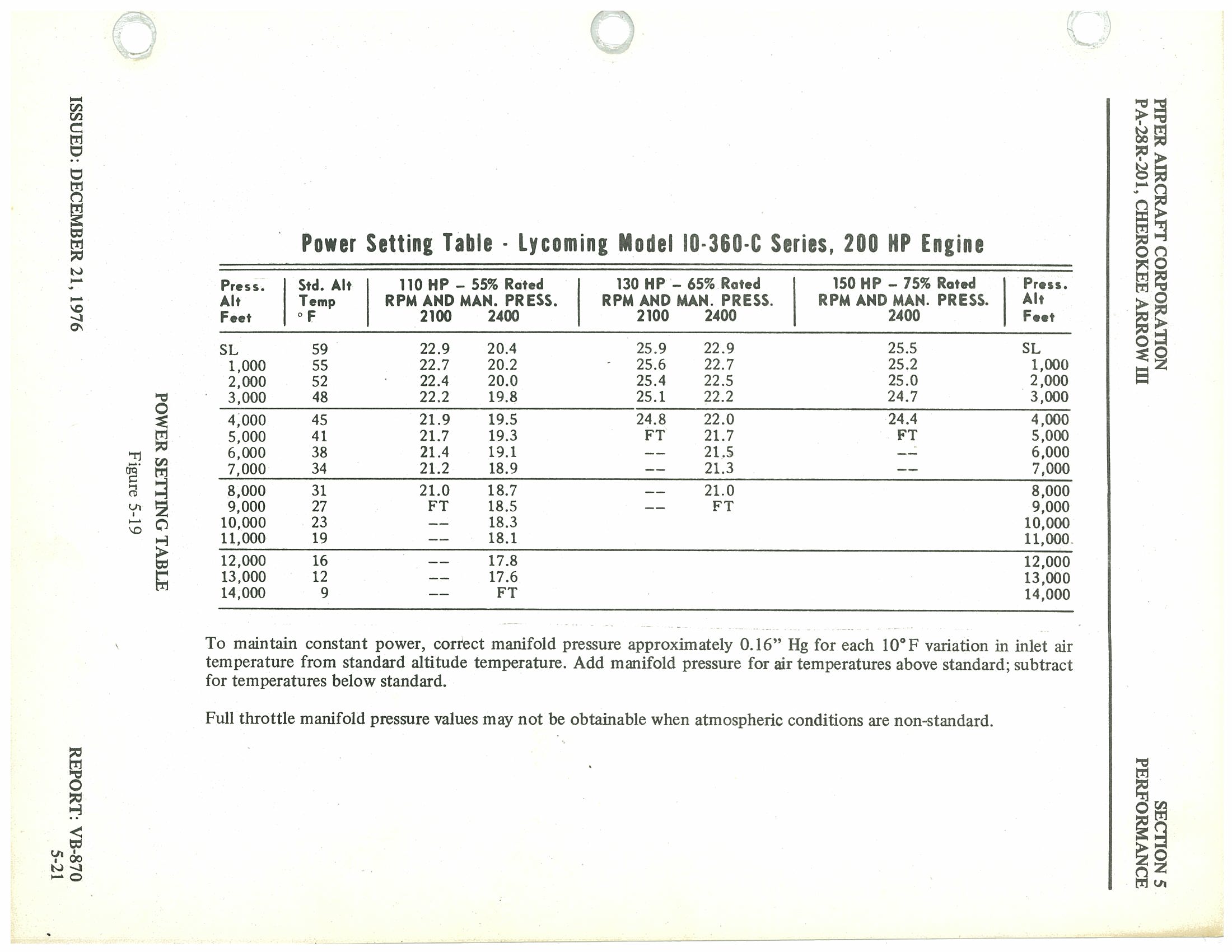
| Press. Alt Feet |
Std. Alt Temp °F |
110 HP – 55% Rated RPM AND MAN. PRESS. |
130 HP – 65% Rated RPM AND MAN. PRESS. |
150 HP – 75% Rated RPM AND MAN. PRESS. |
|||
|---|---|---|---|---|---|---|---|
| 2100 | 2400 | 2100 | 2400 | — | 2400 | ||
| SL | 59 | 22.9 | 20.4 | 25.9 | 22.9 | — | 25.5 |
| 1,000 | 55 | 22.7 | 20.2 | 25.6 | 22.7 | — | 25.2 |
| 2,000 | 52 | 22.4 | 20.0 | 25.4 | 22.5 | — | 25.0 |
| 3,000 | 48 | 22.2 | 19.8 | 25.1 | 22.2 | — | 24.7 |
| 4,000 | 45 | 21.9 | 19.5 | 24.8 | 22.0 | — | 24.4 |
| 5,000 | 41 | 21.7 | 19.3 | FT | 21.7 | — | FT |
| 6,000 | 38 | 21.4 | 19.1 | — | 21.5 | — | — |
| 7,000 | 34 | 21.2 | 18.9 | — | 21.3 | — | — |
| 8,000 | 31 | 21.0 | 18.7 | — | 21.0 | — | — |
| 9,000 | 27 | FT | 18.5 | — | FT | — | — |
| 10,000 | 23 | — | 18.3 | — | — | — | — |
| 11,000 | 19 | — | 18.1 | — | — | — | — |
| 12,000 | 16 | — | 17.8 | — | — | — | — |
| 13,000 | 12 | — | 17.6 | — | — | — | — |
| 14,000 | 9 | — | FT | — | — | — | — |
FT = Full Throttle. Manifold pressure values in inches Hg. All RPM values as indicated in column headers.
Speed Power — Performance Cruise p. 93
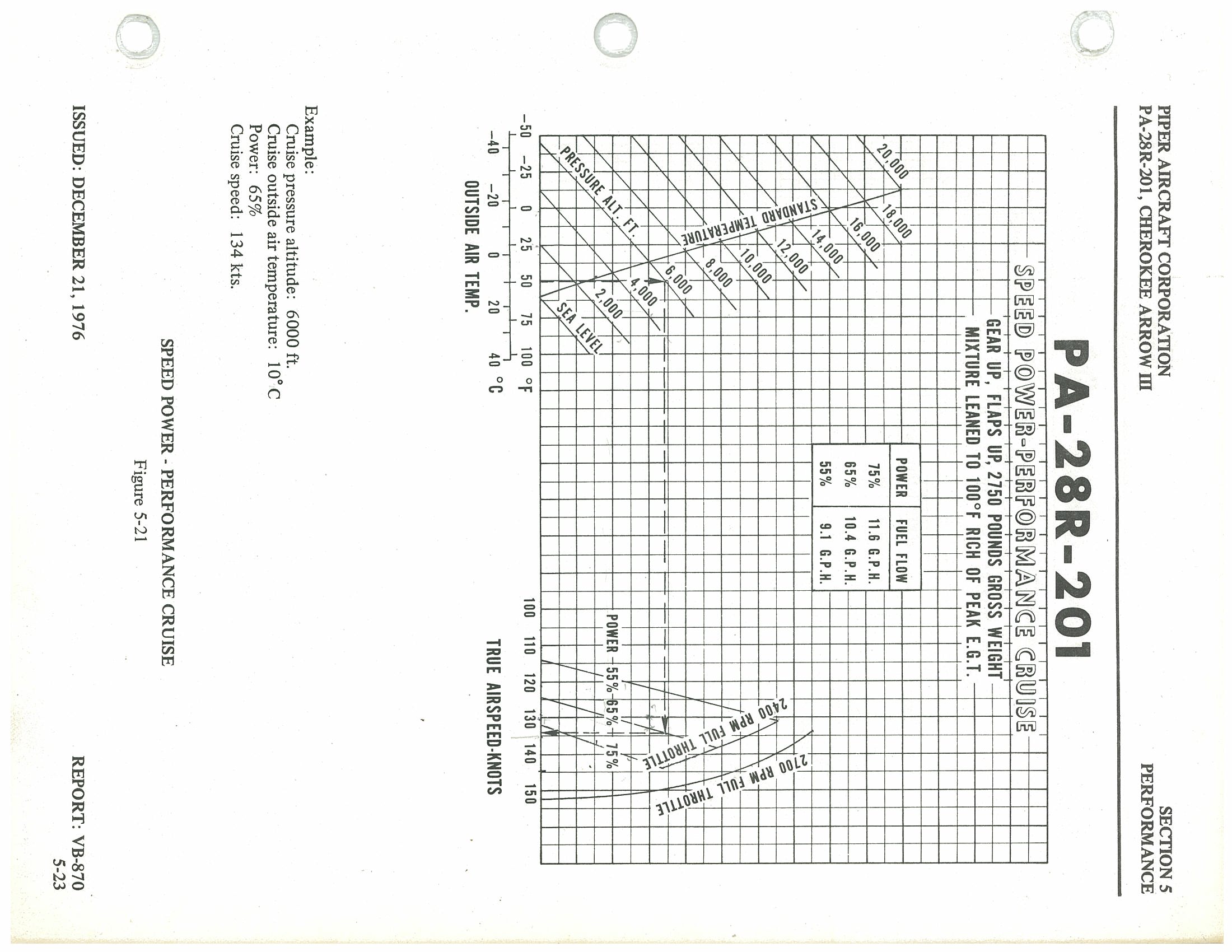
Conditions: Gear Up, Flaps Up, 2750 lbs Gross Weight — Mixture Leaned to 100°F Rich of Peak E.G.T.
| Power Setting | Fuel Flow |
|---|---|
| 75% | 11.6 G.P.H. |
| 65% | 10.4 G.P.H. |
| 55% | 9.1 G.P.H. |
Example — Performance Cruise
- Cruise pressure altitude: 6,000 ft.
- Cruise outside air temperature: 10°C
- Power: 65%
- Cruise speed: 134 kts.
Speed Power — Economy Cruise p. 94
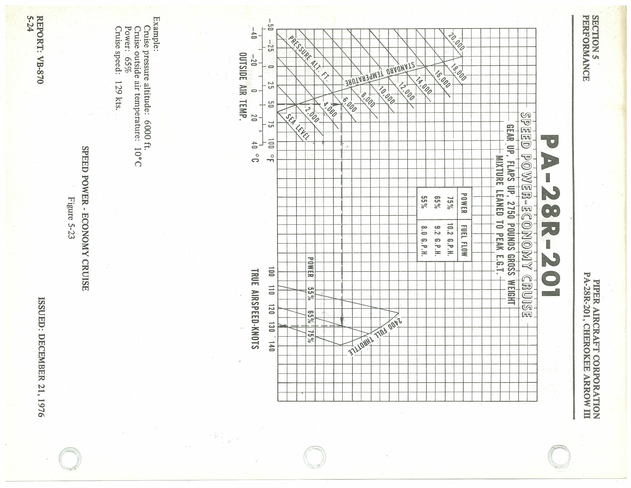
Conditions: Gear Up, Flaps Up, 2750 lbs Gross Weight — Mixture Leaned to Peak E.G.T.
| Power Setting | Fuel Flow |
|---|---|
| 75% | 10.2 G.P.H. |
| 65% | 9.2 G.P.H. |
| 55% | 8.0 G.P.H. |
Example — Economy Cruise
- Cruise pressure altitude: 6,000 ft.
- Cruise outside air temperature: 10°C
- Power: 65%
- Cruise speed: 129 kts.
Range & Endurance Performance Charts p. 95
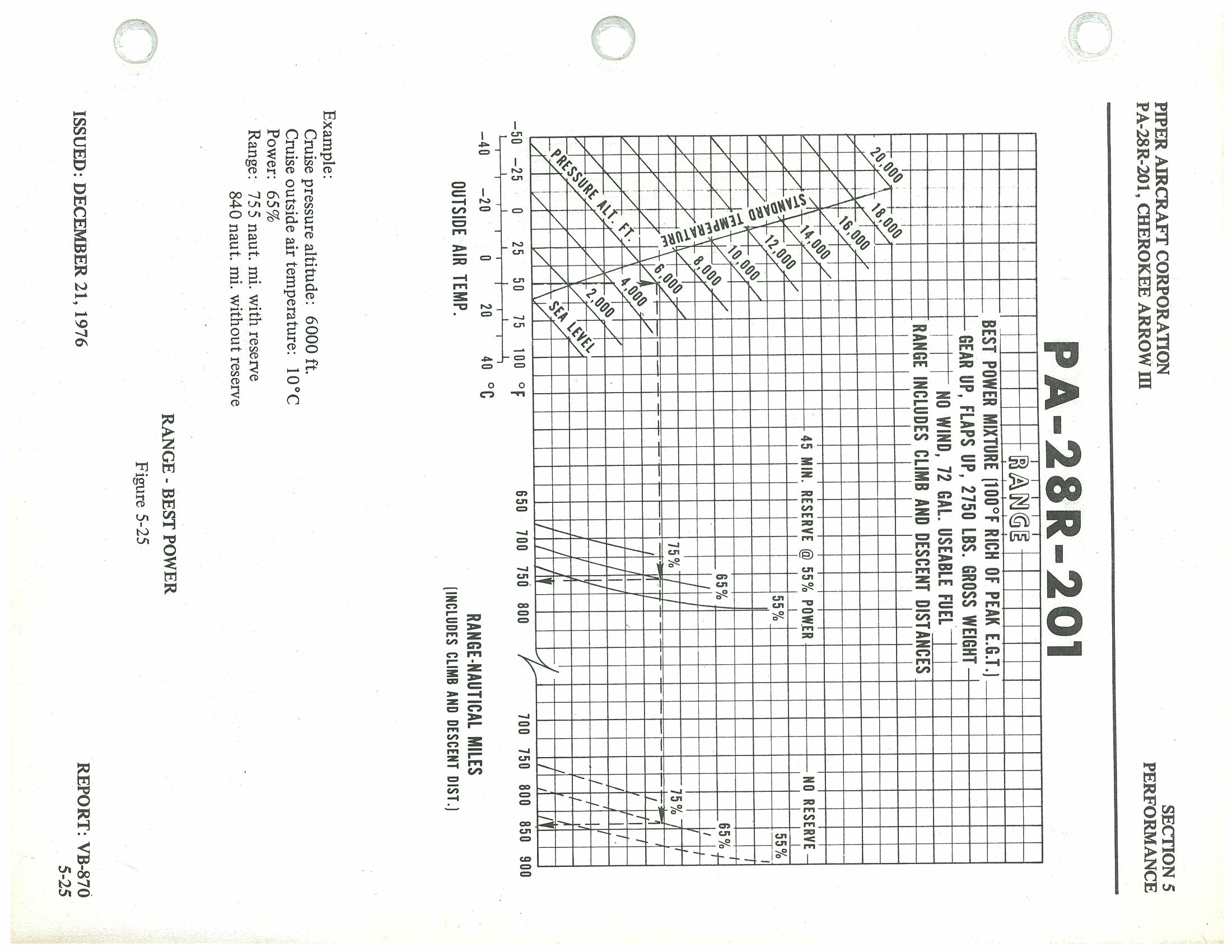
Figure 5-25: Range — Best Power Mixture
Associated Conditions:
- Best Power Mixture (100°F rich of peak E.G.T.)
- Gear Up, Flaps Up
- 2750 lbs. Gross Weight
- No Wind
- 72 gal. useable fuel
- Range includes climb and descent distances
| Power Setting | Range with 45 Min. Reserve @ 55% Power (naut. mi.) | Range — No Reserve (naut. mi.) |
|---|---|---|
| 55% | ~800 | ~880 |
| 65% | ~755 | ~840 |
| 75% | ~700 | ~775 |
Figure 5-27: Range — Best Economy Mixture p. 96
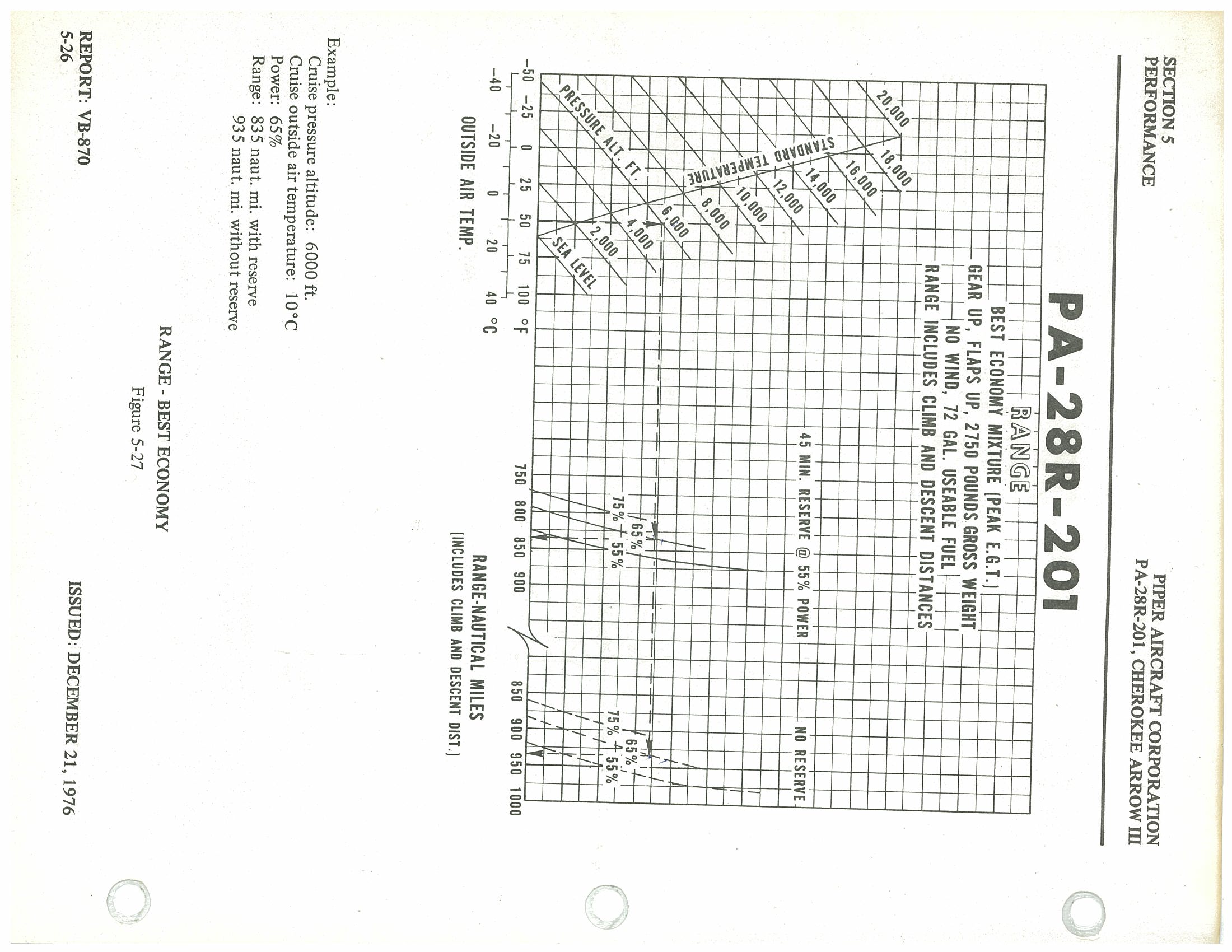
Associated Conditions:
- Best Economy Mixture (Peak E.G.T.)
- Gear Up, Flaps Up
- 2750 lbs. Gross Weight
- No Wind
- 72 gal. useable fuel
- Range includes climb and descent distances
| Power Setting | Range with 45 Min. Reserve @ 55% Power (naut. mi.) | Range — No Reserve (naut. mi.) |
|---|---|---|
| 55% | ~850 | ~950 |
| 65% | ~835 | ~935 |
| 75% | ~775 | ~865 |
Figure 5-29: Endurance p. 97
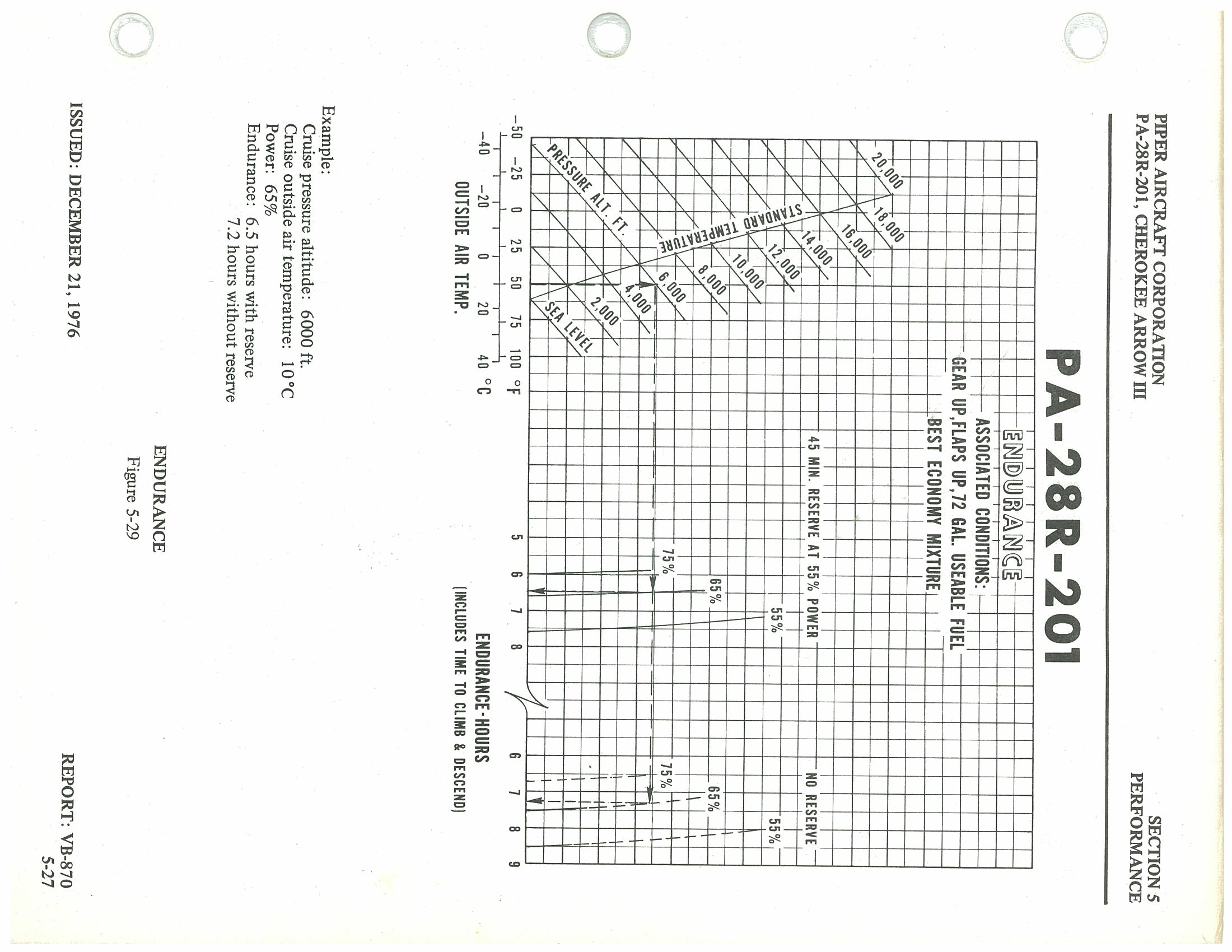
Associated Conditions:
- Gear Up, Flaps Up
- 72 gal. useable fuel
- Best Economy Mixture
- Endurance includes time to climb and descend
| Power Setting | Endurance with 45 Min. Reserve @ 55% Power (hours) | Endurance — No Reserve (hours) |
|---|---|---|
| 55% | ~7.0 | ~8.5 |
| 65% | ~6.5 | ~7.2 |
| 75% | ~5.5 | ~6.2 |
Performance Charts — Descent & Landing p. 98
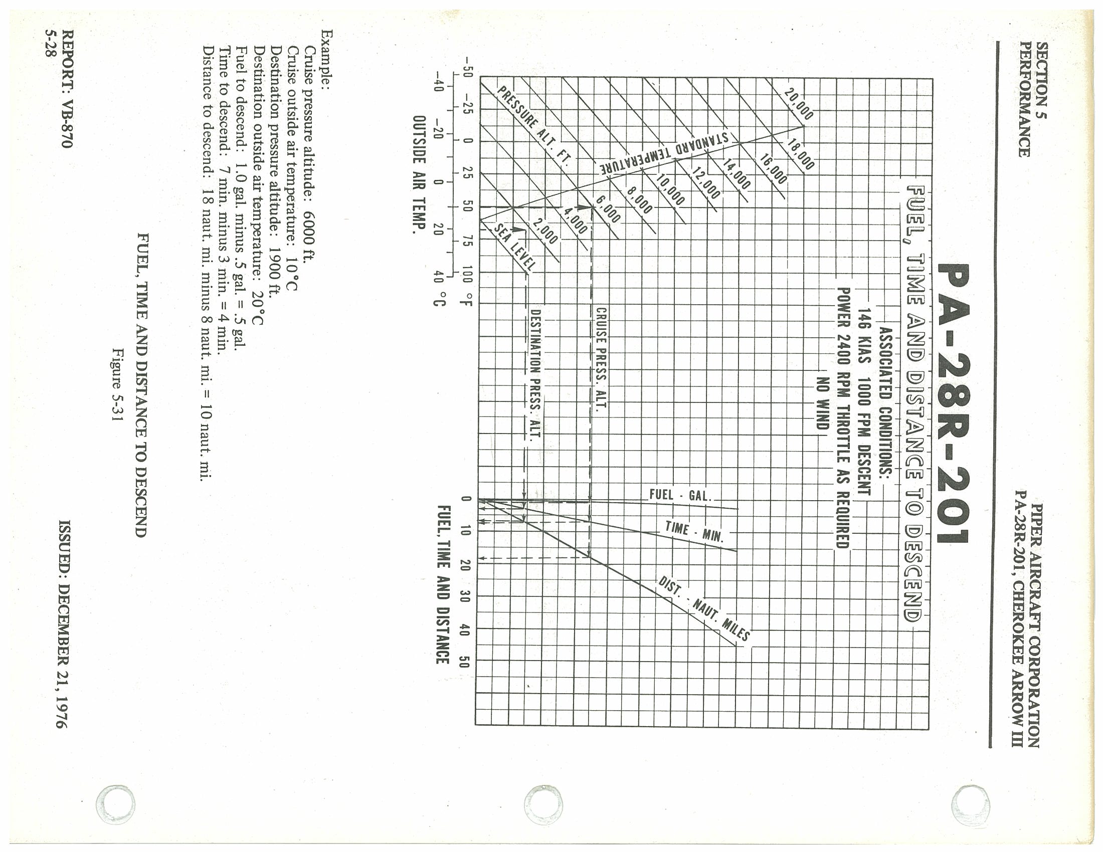
Figure 5-31 — Fuel, Time and Distance to Descend
Associated Conditions:
- 146 KIAS
- 1000 FPM descent
- Power: 2400 RPM, throttle as required
- No wind
| Parameter | Value |
|---|---|
| Cruise pressure altitude | 6,000 ft. |
| Cruise outside air temperature | 10°C |
| Destination pressure altitude | 1,900 ft. |
| Destination outside air temperature | 20°C |
| Fuel to descend | 1.0 gal. − 0.5 gal. = 0.5 gal. |
| Time to descend | 7 min. − 3 min. = 4 min. |
| Distance to descend | 18 naut. mi. − 8 naut. mi. = 10 naut. mi. |
Figure 5-33 — Glide Time & Distance p. 99
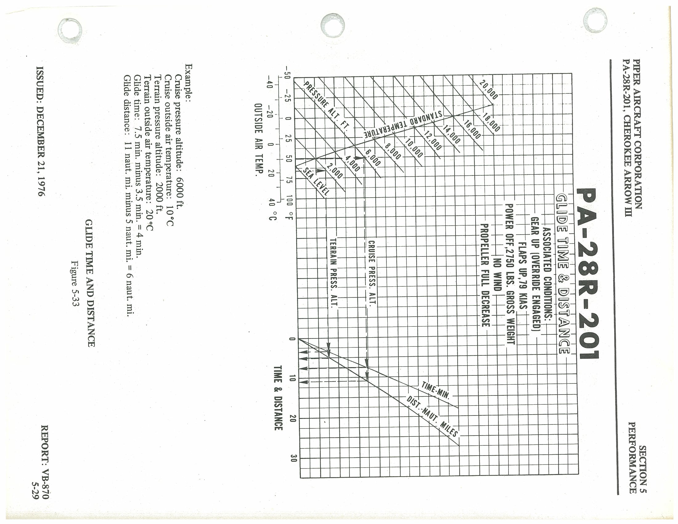
Associated Conditions:
- Gear up (override engaged)
- Flaps up, 79 KIAS
- Power off, 2,750 lbs. gross weight
- No wind
- Propeller full decrease
| Parameter | Value |
|---|---|
| Cruise pressure altitude | 6,000 ft. |
| Cruise outside air temperature | 10°C |
| Terrain pressure altitude | 2,000 ft. |
| Terrain outside air temperature | 20°C |
| Glide time | 7.5 min. − 3.5 min. = 4 min. |
| Glide distance | 11 naut. mi. − 5 naut. mi. = 6 naut. mi. |
Figure 5-35 — Landing Distance Over 50 Foot Barrier p. 100
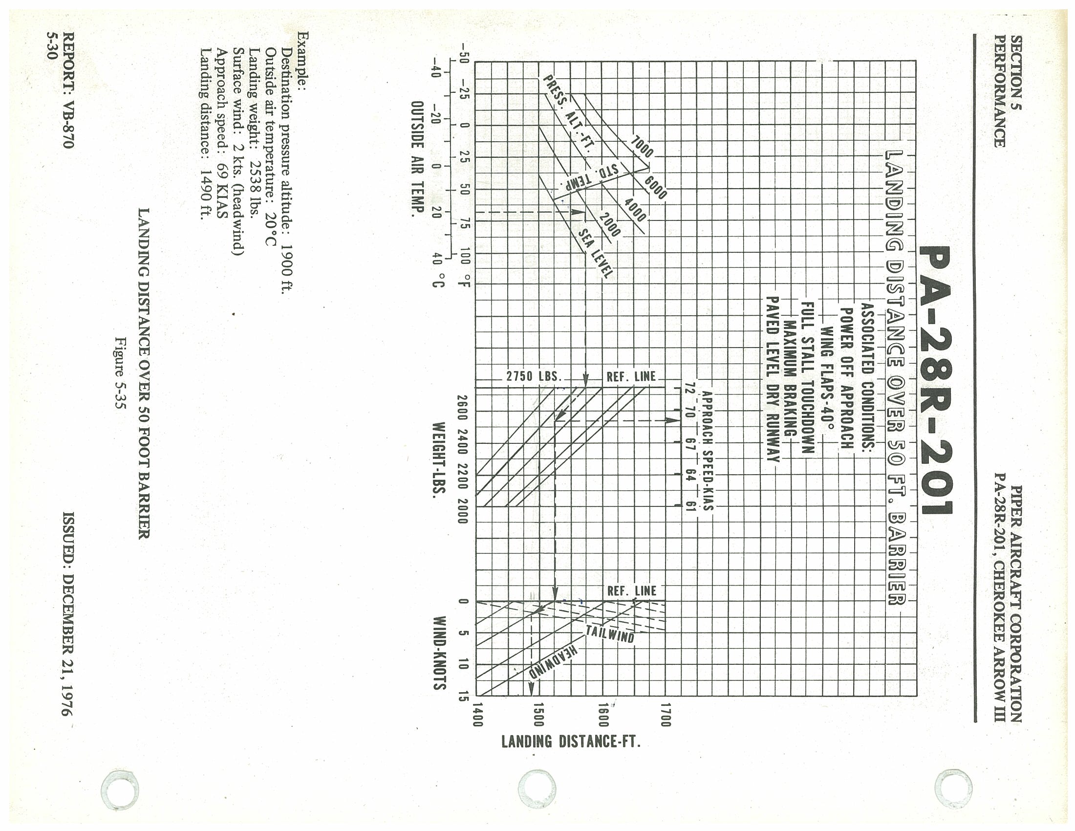
Associated Conditions:
- Power off approach
- Wing flaps: 40°
- Full stall touchdown
- Maximum braking
- Paved, level, dry runway
Approach Speeds (KIAS) by Weight:
| Weight (lbs.) | Approach Speed (KIAS) |
|---|---|
| 2,750 | 72 |
| 2,600 (approx.) | 70 |
| 2,400 (approx.) | 67 |
| 2,200 (approx.) | 64 |
| 2,000 (approx.) | 61 |
| Parameter | Value |
|---|---|
| Destination pressure altitude | 1,900 ft. |
| Outside air temperature | 20°C |
| Landing weight | 2,538 lbs. |
| Surface wind | 2 kts. (headwind) |
| Approach speed | 69 KIAS |
| Landing distance | 1,490 ft. |
Landing Ground Roll Distance p. 101
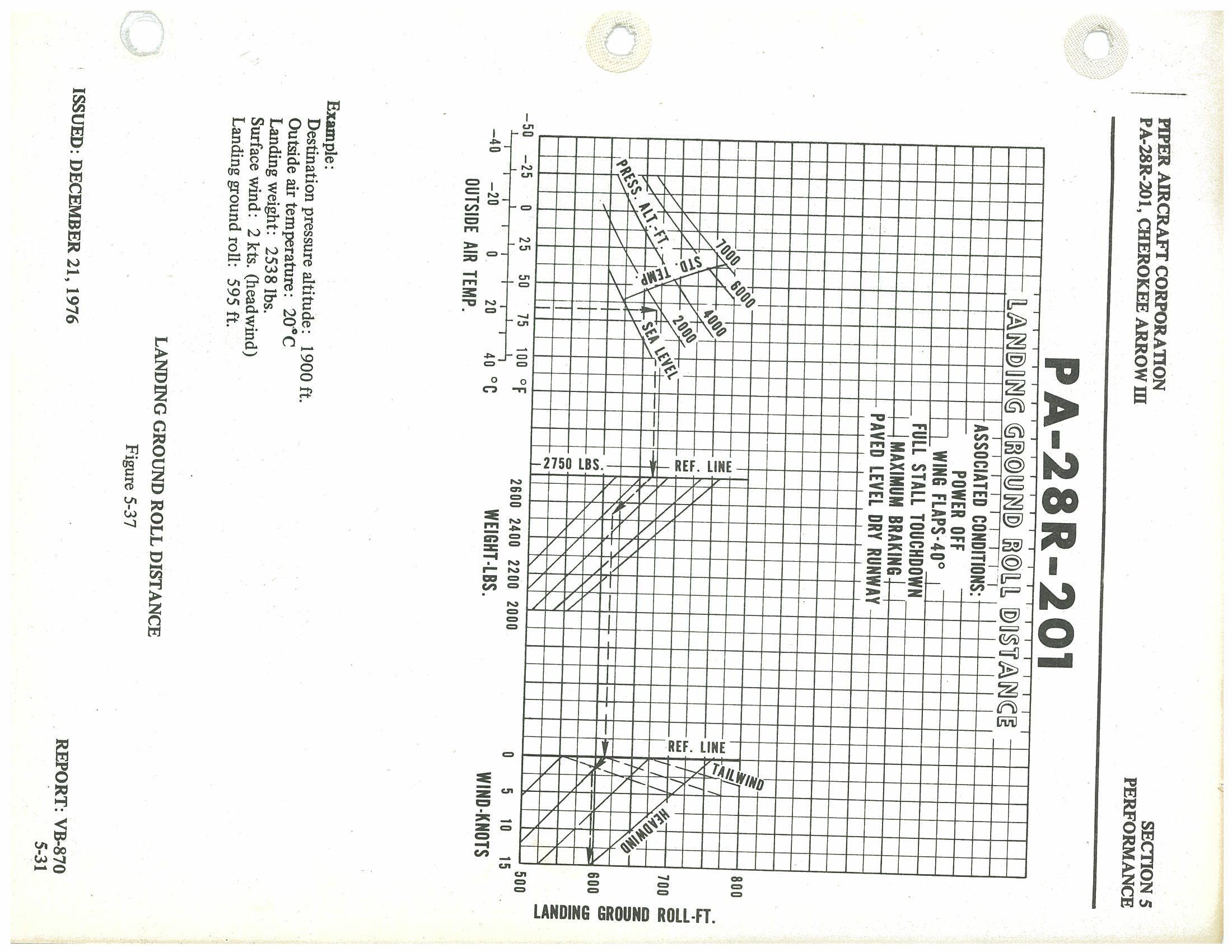
Figure 5-37 Associated Conditions
- Power off
- Wing Flaps — 40°
- Full stall touchdown
- Maximum braking
- Paved level dry runway
Figure 5-37 Example
| Destination pressure altitude | 1,900 ft. |
| Outside air temperature | 20°C |
| Landing weight | 2,538 lbs. |
| Surface wind | 2 kts. (headwind) |
| Landing ground roll | 595 ft. |
Section 6 — Weight and Balance p. 103
Table of Contents
| Paragraph No. | Subject | Page No. |
|---|---|---|
| 6.1 | General | 6-1 |
| 6.3 | Airplane Weighing Procedure | 6-3 |
| 6.5 | Weight and Balance Data and Record | 6-6 |
| 6.7 | Weight and Balance Determination for Flight | 6-11 |
| 6.9 | Equipment List | 6-17 |
| (a) | Propeller and Propeller Accessories | 6-17 |
| (b) | Engine and Engine Accessories | 6-19 |
| (c) | Landing Gear and Brakes | 6-21 |
| (d) | Electrical Equipment | 6-23 |
| (e) | Instruments | 6-25 |
| (f) | Miscellaneous | 6-27 |
| (g) | Engine and Engine Accessories (Optional Equipment) | 6-29 |
| (h) | Propeller and Propeller Accessories (Optional Equipment) | 6-31 |
| (i) | Landing Gear and Brakes (Optional Equipment) | 6-33 |
| (j) | Electrical Equipment (Optional Equipment) | 6-35 |
| (k) | Instruments (Optional Equipment) | 6-37 |
| (l) | Autopilots (Optional Equipment) | 6-39 |
| (m) | Radio Equipment (Optional Equipment) | 6-41 |
| (n) | Miscellaneous (Optional Equipment) | 6-53 |
Section 6 — Weight and Balance p. 104
6.1 General
In order to achieve the performance, safety and good flying characteristics which are designed into the airplane, it must be flown with the weight and center of gravity (C.G.) position within the approved operating range (envelope). Although the airplane offers a tremendous flexibility of loading, it cannot be flown with the maximum number of adult passengers, full fuel tanks and maximum baggage. With the flexibility comes responsibility. The pilot must ensure that the airplane is loaded within the loading envelope before he makes a takeoff.
Misloading carries consequences for any aircraft. An overloaded airplane will not take off, climb or cruise as well as a properly loaded one. The heavier the airplane is loaded, the less climb performance it will have.
A properly loaded airplane, however, will perform as intended. This airplane is designed to provide excellent performance and safety within the flight envelope. Before the airplane is delivered, it is weighed, and a basic empty weight and C.G. location is computed (basic empty weight consists of the standard empty weight of the airplane plus the optional equipment). Using the basic empty weight and C.G. location, the pilot can easily determine the weight and C.G. position for the loaded airplane by computing the total weight and moment and then determining whether they are within the approved envelope.
The basic empty weight and C.G. location are recorded in the Aircraft Log Book, or the Weight and Balance Data Form (Figure 6-5) and the Weight and Balance Record (Figure 6-7). The current values should always be used. Whenever new equipment is added or any modification work is done, the mechanic responsible for the work is required to compute a new basic empty weight and C.G. position and to write these in the Aircraft Log Book and the Weight and Balance Record. The owner should make sure that it is done.
The following pages are forms used in weighing an airplane in production and in computing basic empty weight, C.G. position, and useful load. Note that the useful load includes usable fuel, baggage, cargo and passengers. Following this is the method for computing takeoff weight and C.G.
6.3 Airplane Weighing Procedure p. 106
At the time of delivery, Piper Aircraft Corporation provides each airplane with the basic empty weight and center of gravity location. This data is supplied by Figure 6-5.
The removal or addition of equipment or airplane modifications can affect the basic empty weight and center of gravity. The following is a weighing procedure to determine this basic empty weight and center of gravity location:
(a) Preparation
- Be certain that all items checked in the airplane equipment list are installed in the proper location in the airplane.
- Remove excessive dirt, grease, moisture, foreign items such as rags and tools from the airplane before weighing.
-
Defuel airplane. Then open all fuel drains until all remaining fuel is drained. Operate engine on each tank until all undrainable fuel is used and engine stops. Then add the unusable fuel (5.0 gallons total, 2.5 gallons each wing).
CAUTION: Whenever the fuel system is completely drained and fuel is replenished it will be necessary to run the engine for a minimum of three minutes at 1000 RPM on each tank to insure that no air exists in the fuel supply lines.
- Fill with oil to full capacity.
- Place pilot and copilot seats in fourth (4th) notch, aft of forward position. Put flaps in the fully retracted position and all control surfaces in the neutral position. Tow bar should be in the proper location and all entrance and baggage doors closed.
- Weigh the airplane inside a closed building to prevent errors in scale readings due to wind.
(b) Leveling
- With airplane on scales, block main gear oleo pistons in the fully extended position.
- Level airplane (refer to Figure 6-3) deflating nose wheel tire, to center bubble on level.
(c) Weighing — Airplane Basic Empty Weight p. 107
- With the airplane level and brakes released, record the weight shown on each scale. Deduct the tare, if any, from each reading.
| Scale Position and Symbol | Scale Reading | Tare | Net Weight | |
|---|---|---|---|---|
| Nose Wheel | (N) | |||
| Right Main Wheel | (R) | |||
| Left Main Wheel | (L) | |||
| Basic Empty Weight, as Weighed (T) | — | — | ||
(d) Basic Empty Weight Center of Gravity
-
The following geometry applies to the PA-28R-201 airplane when it is level. Refer to Leveling paragraph 6.3 (b).
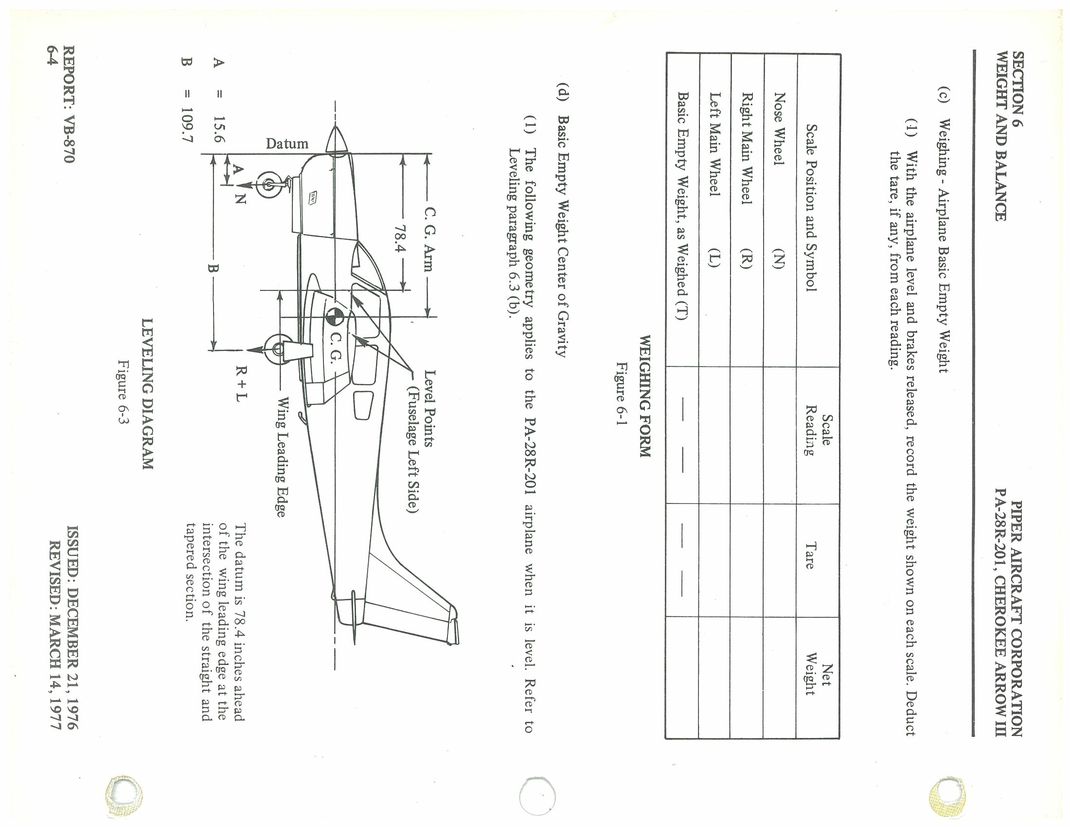 PDF p. 107
LEVELING DIAGRAM — Figure 6-3: Key Dimensions Symbol Description Value A Nose wheel arm (distance from datum to nose wheel) 15.6 inches B Main wheel arm (distance from datum to main wheels) 109.7 inches Datum 78.4 inches ahead of the wing leading edge at the intersection of the straight and tapered section 78.4 in. fwd of wing L.E. N Nose wheel scale reading (net) — R + L Right + Left main wheel scale readings (net) — Level Points Fuselage left side — - p. 108
The basic empty weight center of gravity (as weighed including optional equipment, full oil and unusable fuel) can be determined by the following formula:
C.G. Arm = N(A) + (R+L)(B) inches
TWhere: T = N + R + L
CG Formula Variables Variable Definition N Net weight on nose wheel scale (lbs) R Net weight on right main wheel scale (lbs) L Net weight on left main wheel scale (lbs) T Total weight = N + R + L (lbs) A Nose wheel arm = 15.6 inches B Main wheel arm = 109.7 inches
6.5 Weight and Balance Data and Record p. 109
The Basic Empty Weight, Center of Gravity Location and Useful Load listed in Figure 6-5 are for the airplane as delivered from the factory. These figures apply only to the specific airplane serial number and registration number shown.
The basic empty weight of the airplane as delivered from the factory has been entered in the Weight and Balance Record (Figure 6-7). This form is provided to present the current status of the airplane basic empty weight and a complete history of previous modifications. Any change to the permanently installed equipment or modification which affects weight or moment must be entered in the Weight and Balance Record.
Weight and Balance Data Form — Figure 6-5 p. 110
Airplane Basic Empty Weight
| Item | Weight (Lbs) | C.G. Arm (Inches Aft of Datum) | Moment (In-Lbs) |
|---|---|---|---|
| Standard Empty Weight* (Computed) | 1593.0 | 83.3 | 132655 |
| Optional Equipment | 198.5 | 113.1 | 22450 |
| Basic Empty Weight | 1791.5 | 86.6 | 155105 |
*The standard empty weight includes full oil capacity and 5.0 gallons of unusable fuel.
Airplane Useful Load — Normal Category Operation
(Gross Weight) − (Basic Empty Weight) = Useful Load
(2750 lbs) − (1791.5 lbs) = 958.5 lbs
Weight and Balance Revision p. 112
Revision — Previous Values (Superseded)
| Item | Weight (Lbs) | Arm (In.) | Moment (In-Lbs) |
|---|---|---|---|
| Aircraft | 1791.5 | 86.6 | 155105 |
| ELT battery pack & kit | 1.8 | 236.2 | 425.16 |
| Additional items marked "Superceded" in original document | |||
| Total (Superseded) | 1793.3 | 86.7 | 155530.16 |
Revised Empty Weight Summary
| Empty Weight | 1793.3 lbs |
|---|---|
| Empty Wt. C.G. | 86.7 inches aft of datum |
| Useful Load (Normal) | 956.7 lbs |
Weight and Balance Revision Records p. 113
Prepared by: North East Gyro & Autopilot Co. (Dyer's Aircraft Service, Inc.) — FAA Repair Station 163-6
Equipment Installation — 3/23/84
Make: Piper Model: PA 28R-201 Serial #: 28R-7837134 Registration #: N3757M
| Previous (Old) Empty Weight Data | |||
|---|---|---|---|
| Old Empty Weight | 1793.3 lbs. | Old C.G. | 86.7 |
| Old Useful Load | 956.7 lbs. | Old Moment | 155530.16 |
Installed Equipment: 3M (Ryan) Stormscope WX8
| Unit | Weight (lbs.) | Arm | Moment |
|---|---|---|---|
| Processor Display Unit | (+) 2.0 | 60.0 | (+) 120.0 |
| Antenna | (+) 2.0 | 145.0 | (+) 290.0 |
| Total Weight Installed | (+) 4.0 | — | — |
| Total Moment Added | — | — | (+) 410.0 |
| Revised (New) Empty Weight Data — After 3/23/84 Installation | |||
|---|---|---|---|
| New Empty Weight | 1797.3 lbs. | New C.G. | 86.76 |
| New Useful Load | 952.7 lbs. | New Moment | 155940.16 |
Weight and Balance — 2/7/90 p. 114
Prepared by: Cherry Hill Flying Service, 348 Botons Mill Rd., Cherry Hill, NJ 08034 | A&P: C. S. Platt, 13 Virgina Dr., Whiting, NJ 08759, A&P 207603
Aircraft: Piper PA-28R-201 Reg: N3757M S/N: 28R-7837134
| Item | Empty Wt. (lbs.) | C.G. | Moment |
|---|---|---|---|
| OAEW (Old Actual Empty Weight) | 1797.3 | 86.76 | 155940.16 |
| Add: Skylite Landing Lite | 5.00 | 92.4 | 462.00 |
| NAEW (New Actual Empty Weight) | 1802.3 | 86.8 | 156402.16 |
New Useful Load: 947.7 lbs.
Weight and Balance — 3-4-93 p. 115
Prepared by: Cherry Hill Flying Service, 348 Bortons Mill Road, Cherry Hill, NJ 08034 | F. W. Holler, Jr. A&P 479-22-0620
Aircraft: Piper Arrow PA-28R-201 Reg: N3757M S/N: 28R-7837134
| Item | Weight (lbs.) | CG | Moment |
|---|---|---|---|
| OAEW | 1802.3 | 86.8 | 156402.16 |
| Remove: King KR-85 ADF & Rack | -3.8 | — | -223.8 |
| Remove: King KR-85 ADF Indicator | -1.4 | — | -86.0 |
| Add: King KR-86 ADF & Rack | 3.9 | — | 233.6 |
| Add: Garmin GPS-100 AVD | 2.4 | — | 146.2 |
| Add: Garmin GPS-100 Antenna | 0.5 | — | 61.9 |
| Add: PEMALL Fire Extinguisher | 4.8 | — | 446.4 |
| NAEW (New Actual Empty Weight) | 1808.7 | 86.79 | 156980.46 |
New Useful Load: 941.3 lbs.
Weight & Balance Revision Record p. 116
CG–Arm–Moment/Weight
Equipment Added
| Item | Weight (lb) | Arm (in) | Moment |
|---|---|---|---|
| Garmin GNS 430 | 6.5 | 56 | 364 |
| Garmin 106A | 1.04 | 60 | 62.4 |
| GTX 327 | 3 | 58 | 174 |
| GMA 340 | 1.7 | 60 | 102 |
| Total | 12.24 | 57.39 | 702.4 |
Equipment Removed
| Item | Weight (lb) | Arm (in) | Moment |
|---|---|---|---|
| King KX 170B | 7.4 | 56 | 414.4 |
| King KI 520 | 1.9 | 60 | 114 |
| KMA 20 | 2.6 | 60 | 156 |
| KT 78A | 3 | 56 | 168 |
| KR 86 | 6.5 | 86 | 559 |
| GPS-100 | 2.4 | 60.9 | 146.16 |
| KN-77 | 4.6 | 140 | 644 |
| SPA 400 | 1 | 60 | 60 |
| Total | 29.4 | 76.92 | 2,261.56 |
New Empty Weight: 1,791.54 lb
New Moment: 155,421.30
New CG: 86.75 in
New Useful Load: 958.5 lb
Net Change in Empty Weight: −17.16 lb
Computed by Eagle's Nest Aviation — Quality Aircraft Services, 1465 South State Street, Ukiah, CA 95482 — Phone: 707-462-0110
Weight and Balance Record — Figure 6-7 p. 117
Aircraft: PA-28R-201 | Serial Number: 28R-7837134 | Registration: N3757M
| Date | Item No. In/Out | Description of Article or Modification | Added (+) | Removed (−) | Running Basic Empty Weight | Page No. | |||||
|---|---|---|---|---|---|---|---|---|---|---|---|
| Wt. (lb) | Arm (in) | Moment /100 | Wt. (lb) | Arm (in) | Moment /100 | Wt. (lb) | Moment /100 | ||||
| As Delivered | 1791.5 | 155530.16 | |||||||||
| 10/27/[8x] | In ✕ | ELT Battery Pack + Kit | 1.8 | 236.2 | 425.16 | 1793.3 | 155940.16 | ||||
| 3/23/[8]4 | In ✕ | 3M Stormscope Processor Display | 2.0 | 60 | 120.0 | 1797.3 | 155940.16 | ||||
| 3/6/[8x] | In ✕ | Antenna | 2.0 | 145 | 290.0 | 1803.3 | 156402.16 | ||||
| 2/9/[9x] | In ✕ | Landing Light @ Wing | 5.0 | 93.4 | 46.2 | 1798.5 | 156178.30 | ||||
| 3-2-[9]3 | 185 | King KR-85 ADF Control Unit @ Rack | 3.8 | 58.9 | 223.8 | 1797.1 | 156092.36 | ||||
| 3-2-[9]3 | 185 | King KR-25 ADF Indicator | 1.4 | 61.4 | 86.0 | 1801.0 | 156325.90 | ||||
| 3-2-[9]3/187 | King KR-86 ADF Control Unit @ Rack | 3.9 | 59.9 | 483.6 | 1803.4 | 156472.16 | |||||
| 3-2-[9]3/145 | Garmin GNS-100 AVC @ Rack | 1.4 | 66.9 | 146.2 | 1803.9 | 156534.06 | |||||
| 3-2-[9]3/145 | Garmin GNS-100 AVC Antenna | 0.5 | 143.8 | 6.9 | 1803.9 | 156534.06 | |||||
| 3/1/[9]3 ✕ | Penn All Halon Fire Extinguisher | 4.8 | 93.0 | 446.4 | 1808.7 | 156980.46 | |||||
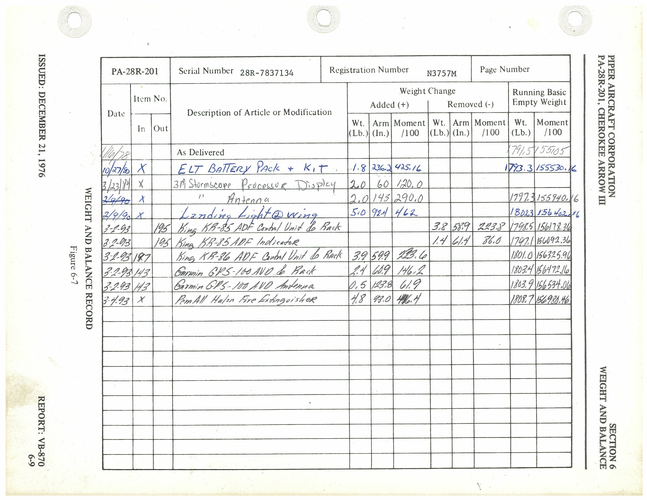
Weight and Balance Record (Continuation Sheet) — Figure 6-7 (cont) p. 118
Section 6 — Weight and Balance | PA-28R-201, Cherokee Arrow III | Report: VB-870, p. 6-10 | Issued: December 21, 1976
| Date | Item No. In/Out | Description of Article or Modification | Added (+) | Removed (−) | Running Basic Empty Weight | Page No. | |||||
|---|---|---|---|---|---|---|---|---|---|---|---|
| Wt. (lb) | Arm (in) | Moment /100 | Wt. (lb) | Arm (in) | Moment /100 | Wt. (lb) | Moment /100 | ||||
| (Blank continuation sheet — no entries recorded) | |||||||||||
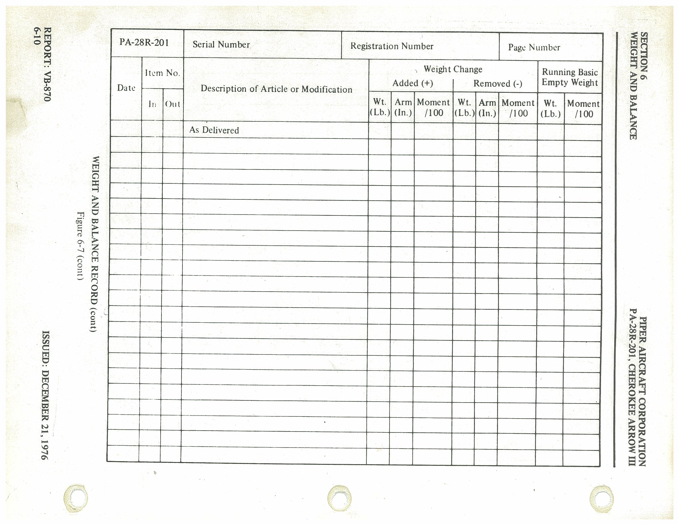
6.7 Weight and Balance Determination for Flight p. 119
- Add the weight of all items to be loaded to the basic empty weight.
- Use the Loading Graph (Figure 6-13) to determine the moment of all items to be carried in the airplane.
- Add the moment of all items to be loaded to the basic empty weight moment.
- Divide the total moment by the total weight to determine the C.G. location.
- By using the figures of item (a) and item (d) (above), locate a point on the C.G. range and weight graph (Figure 6-15). If the point falls within the C.G. envelope, the loading meets the weight and balance requirements.
Sample Loading Problem (Normal Category) — Figure 6-9
| Item | Weight (Lbs) | Arm Aft Datum (Inches) | Moment (In-Lbs) |
|---|---|---|---|
| Basic Empty Weight | 1791.5 | 86.6 | 155105 |
| Pilot and Front Passenger | 340.0 | 80.5 | 27370 |
| Passengers (Rear Seats) | 340.0 | 118.1 | 40154 |
| Fuel (72 Gallon Maximum) | 278.5 | 95.0 | 26458 |
| Baggage | — | 142.8 | — |
| Moment due to Retraction of Landing Gear | — | — | 819 |
| Total Loaded Airplane | 2750 | 90.9 | 249906 |
The center of gravity (C.G.) of this sample loading problem is at 90.9 inches aft of the datum line. Locate this point (90.9) on the C.G. range and weight graph. Since this point falls within the weight-C.G. envelope, this loading meets the weight and balance requirements.
Weight and Balance Loading Form — Figure 6-11 p. 120
Totals must be within approved weight and C.G. limits. It is the responsibility of the airplane owner and the pilot to insure that the airplane is loaded properly. The Basic Empty Weight C.G. is noted on the Weight and Balance Data Form (Figure 6-5). If the airplane has been altered, refer to the Weight and Balance Record for this information.
| Item | Weight (Lbs) | Arm Aft Datum (Inches) | Moment (In-Lbs) |
|---|---|---|---|
| Basic Empty Weight | |||
| Pilot and Front Passenger | 80.5 | ||
| Passengers (Rear Seats) | 118.1 | ||
| Fuel (72 Gallon Maximum) | 95.0 | ||
| Baggage | 142.8 | ||
| Moment due to Retraction of Landing Gear | — | — | 819 |
| Total Loaded Airplane |
Loading Graph — Figure 6-13 p. 121
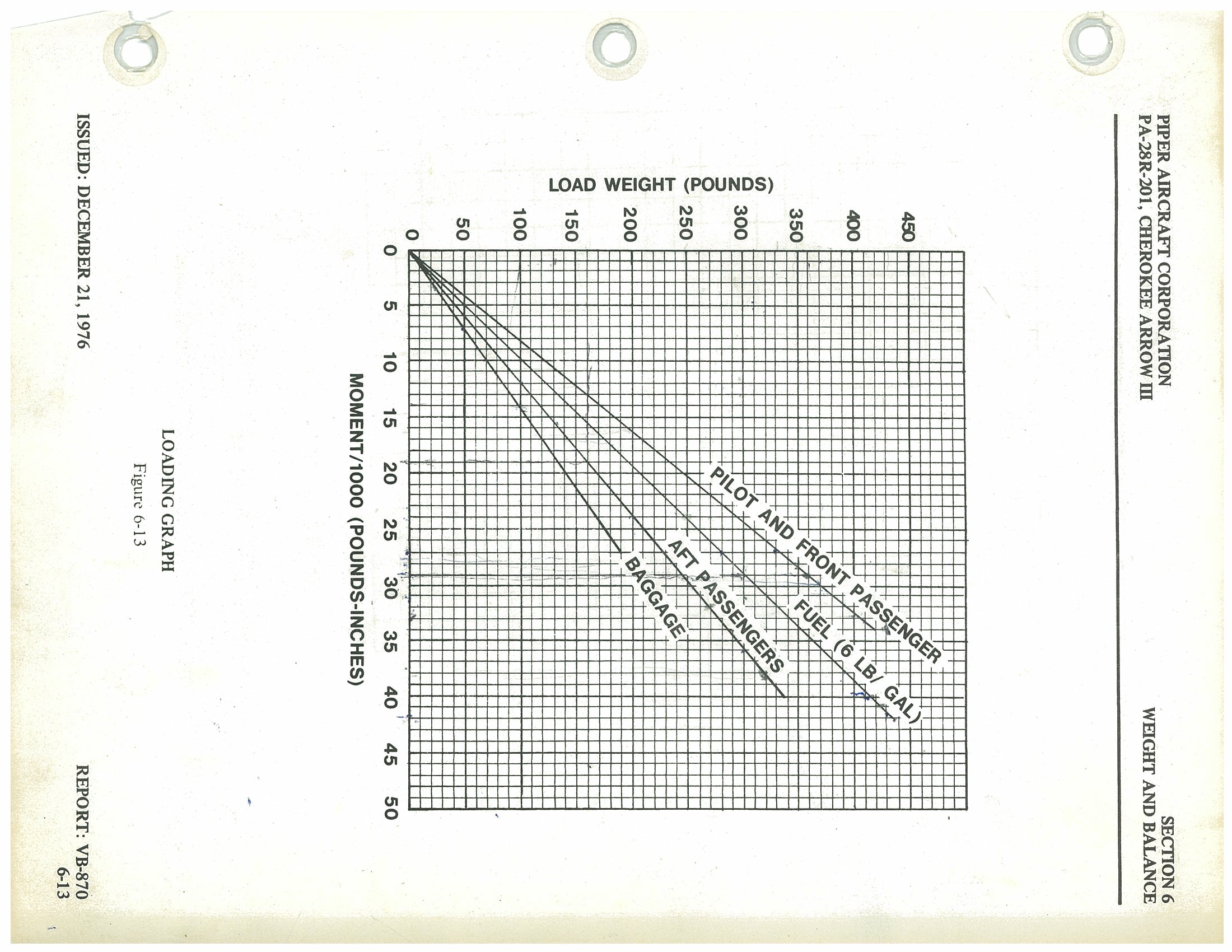
| Load Weight (lbs) | Pilot & Front Pax Moment/1000 (lb-in) | Fuel (6 lb/gal) Moment/1000 (lb-in) | Aft Passengers Moment/1000 (lb-in) | Baggage Moment/1000 (lb-in) |
|---|---|---|---|---|
| 50 | ~4.0 | ~4.8 | ~5.9 | ~7.1 |
| 100 | ~8.1 | ~9.5 | ~11.8 | ~14.3 |
| 150 | ~12.1 | ~14.3 | ~17.7 | ~21.4 |
| 200 | ~16.1 | ~19.0 | ~23.6 | ~28.6 |
| 250 | ~20.1 | ~23.8 | ~29.5 | ~35.7 |
| 300 | ~24.2 | ~28.5 | ~35.4 | ~42.8 |
| 350 | ~28.2 | ~33.3 | ~41.3 | — |
| 400 | ~32.2 | ~38.0 | — | — |
| 432 (max fuel 72 gal) | — | ~41.0 | — | — |
C.G. Range and Weight p. 122
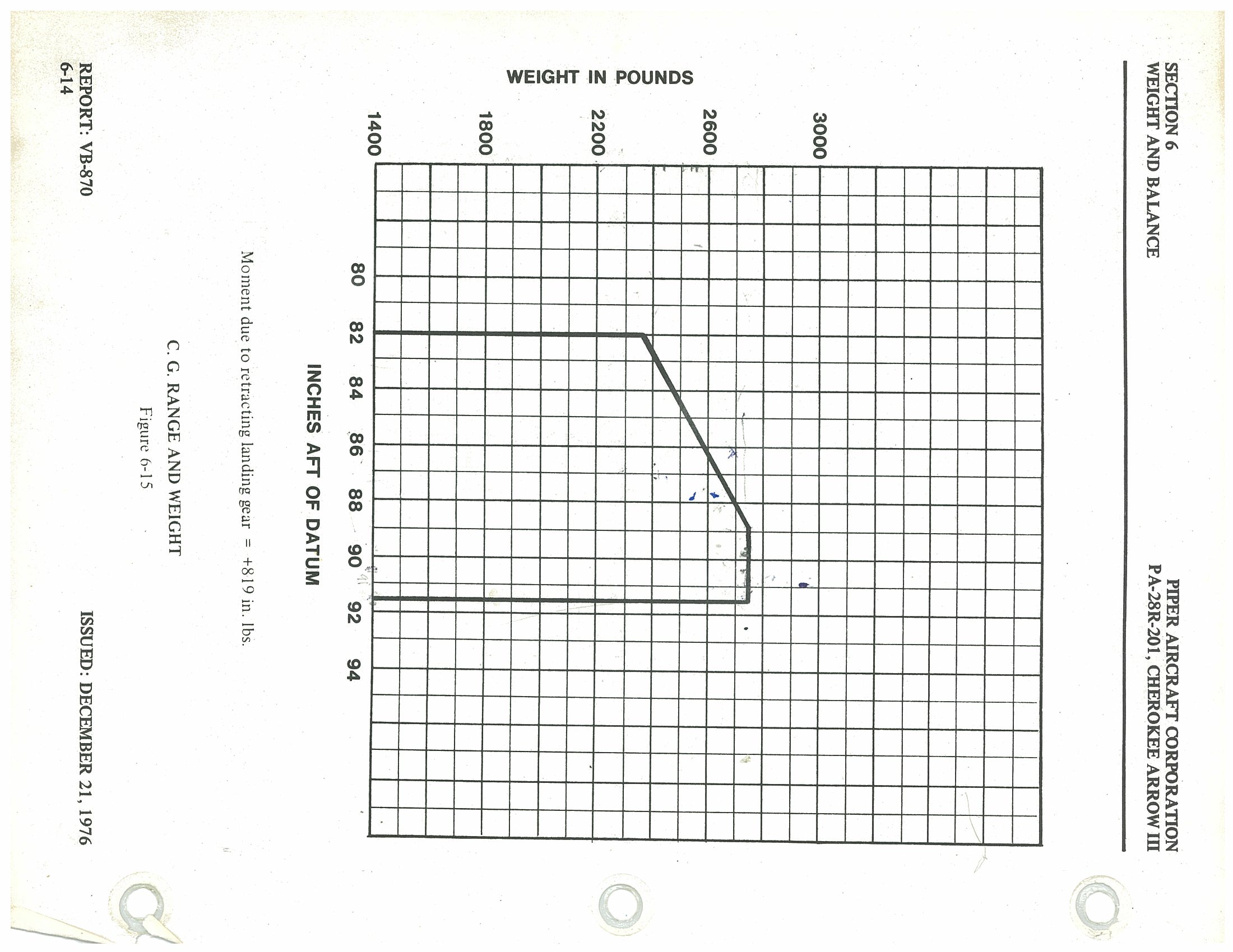
Moment due to retracting landing gear = +819 in. lbs.
The C.G. envelope (from Figure 6-15) defines the following boundaries:
| Weight (lbs) | Forward CG Limit (in. aft of datum) | Aft CG Limit (in. aft of datum) |
|---|---|---|
| 2,300 (min envelope weight at forward limit) | 82.0 | — |
| 2,750 (max gross weight) | 86.5 (approx.) | 91.0 |
| All weights below 2,750 lbs (aft limit) | — | 91.0 |
p. 123 This page intentionally left blank.
p. 124 This page intentionally left blank.
6.9 Equipment List p. 125
The following is a list of equipment which may be installed in the PA-28R-201. It consists of those items used for defining the configuration of an airplane when the basic empty weight is established at the time of delivery. Only those standard items which are alternate standard items and those required to be listed by the certificating authority (FAA) are presented. Items marked with an "X" are those items which were installed on the airplane described below as delivered by the manufacturer.
(a) Propeller and Propeller Accessories
| Item No. | Item | Mark if Instl. | Weight (Pounds) | Arm (In.) Aft Datum | Moment (Lb-In.) |
|---|---|---|---|---|---|
| 1 | a. Propeller, McCauley B2D34C213/90DHA-16 Cert. Basis - TC P7EA |
— | 49.0 | -1.9 | -93 |
| b. Propeller, Hartzell HC-C2YK-1( )F/F7666A-2R Cert. Basis - TC P920 |
— | 55.0 | -1.9 | -105 | |
| 2 | a. Spinner and Attachment Plate Installation PAC Dwg. 35828-2 (For McCauley Prop.) Cert. Basis - TC 2A13 |
— | 4.7 | -2.2 | -10 |
| b. Spinner and Attachment Plate Installation PAC Dwg. 99374 (For Hartzell Prop.) Cert. Basis - TC 2A13 |
— | 5.0 | -2.2 | -11 | |
| 3 | Propeller Governor, Hartzell Model F-2-7 ( ) Cert. Basis - TC P7EA |
— |
(b) Engine and Engine Accessories p. 127
| Item No. | Item | Mark if Instl. | Weight (Pounds) | Arm (In.) Aft Datum | Moment (Lb-In.) |
|---|---|---|---|---|---|
| 5 | Lycoming Model IO-360-C1C6 Cert. Basis - TC 1E10 |
— |
(c) Landing Gear and Brakes p. 129
| Item No. | Item | Mark if Instl. | Weight (Pounds) | Arm (In.) Aft Datum | Moment (Lb-In.) |
|---|---|---|---|---|---|
| 11 |
Two Main Wheel Assemblies a. Cleveland Aircraft Products Wheel Assy. No. 40-86 Brake Assy. No. 30-55 Cert. Basis - TSO C26a |
— | — | — | — |
|
b. 6.00-6 Type III 6 Ply Rating Tires with Regular Tubes Cert. Basis - TSO C62 |
— | — | — | — | |
| 13 |
Nose Wheel Assembly a. Cleveland Aircraft Products Wheel Assy. No. 40-77 Cert. Basis - TSO C26a |
— | 2.6 | 15.5 | 40 |
|
b. McCauley Industrial Corp. Wheel Assy. No. D-30500 Cert. Basis - TSO C26b |
X | 3.6 | 15.5 | 56 | |
|
c. 5.00-5 Type III 4 Ply Rating Tire with Regular Tube Cert. Basis - TSO C62 |
— | — | — | — |
PDF pages 128 and 130 are intentionally left blank (Section 6 — Weight and Balance, Report VB-870, pages 6-20 and 6-22).
(d) Electrical Equipment p. 131
| Item No. | Item | Mark if Instl. | Weight (Pounds) | Arm (In.) Aft Datum | Moment (Lb-In.) |
|---|---|---|---|---|---|
| — No items listed for Electrical Equipment on this page — | |||||
(e) Instruments p. 133
| Item No. | Item | Mark if Instl. | Weight (Pounds) | Arm (In.) Aft Datum | Moment (Lb-In.) |
|---|---|---|---|---|---|
| 21 | Altimeter, Piper PS50008-50-2 Cert. Basis - TSO C10b |
||||
| 23 | Airspeed Indicator, Piper PS50049-32S Cert. Basis - TSO C2b |
||||
| 25 | Manifold Pressure and Fuel Flow Indicator, Piper PS50031-6 Cert. Basis - TSO C45, C47 |
||||
| 27 | Compass Cert. Basis - TSO C7c |
(f) Miscellaneous p. 135
| Item No. | Item | Mark if Instl. | Weight (Pounds) | Arm (In.) Aft Datum | Moment (Lb-In.) |
|---|---|---|---|---|---|
| 33 | Front Seat Belts (2) Piper PS50039-4-2A Cert. Basis - TSO C22f |
||||
| 35 | Rear Seat Belts (2) Piper PS50039-4-3A Cert. Basis - TSO C22f |
Pages 6-26 and 6-28 (PDF pp. 134, 136) intentionally left blank.
(g) Engine and Engine Accessories (Optional Equipment) p. 137
| Item No. | Item | Mark if Instl. | Weight (Pounds) | Arm (In.) Aft Datum | Moment (Lb-In.) |
|---|---|---|---|---|---|
| No items listed — this table is provided for aircraft-specific equipment entry. | |||||
(h) Propeller and Propeller Accessories (Optional Equipment) p. 139
| Item No. | Item | Mark if Instl. | Weight (Pounds) | Arm (In.) Aft Datum | Moment (Lb-In.) |
|---|---|---|---|---|---|
| No items listed — this table is provided for aircraft-specific equipment entry. | |||||
(i) Landing Gear and Brakes (Optional Equipment) p. 141
| Item No. | Item | Mark if Instl. | Weight (Pounds) | Arm (In.) Aft Datum | Moment (Lb-In.) |
|---|---|---|---|---|---|
| No items listed in original document for this category. | |||||
(j) Electrical Equipment — Optional Equipment p. 143
| Item No. | Item | Mark if Instl. | Weight (Lbs.) | Arm (In.) Aft Datum | Moment (Lb-In.) |
|---|---|---|---|---|---|
| 79 | Instrument Panel Lights Cert. Basis - TC 2A13 |
✗ | 0.3 | 62.8 | 19 |
| 81 | Instrument Light, Grimes 15-0083-7 Cert. Basis - TC 2A13 |
✗ | 0.1 | 99.0 | 10 |
| 83 | Cabin Light Cert. Basis - TC 2A13 |
✗ | 0.3 | 99.0 | 30 |
| 85 | Landing Light, G.E. Model 4509 Cert. Basis - TC 2A13 |
✗ | 0.5 | 10.0 | 5 |
| 87 | Navigation Lights (Wing) (2), Grimes Model A1285 (Red and Green) Cert. Basis - TC 2A13 |
— | 0.4 | 106.6 | 43 |
| 89 | Navigation Light (Rear) (1), Grimes Model A2064 (White) Cert. Basis - TC 2A13 |
✗ | 0.2 | 281.0 | 56 |
| 91 | Rotating Beacon Cert. Basis - TC 2A13 |
✗ | 1.5 | 263.4 | 395 |
| 93 | Anti-Collision Lights (Wing Tip) (Whelen) Cert. Basis - STC SA615EA |
✗ | 5.7 | 157.9 | 900 |
| 95 | Heated Pitot Head Cert. Basis - TC 2A13 |
✗ | 0.4 | 100.0 | 40 |
| 97 | Piper Pitch Trim, Piper Dwg. 67496-3 Cert. Basis - TC 2A13 |
✗ | 4.3 | 155.3 | 668 |
| 99 | Battery 12V 35 A.H., Rebat R35 (Wt. 27.2 lbs.) Cert. Basis - TC 2A13 |
✗ | *5.3 | 168.0 | 890 |
*Weight and moment difference between standard and optional equipment.
(j) Electrical Equipment — Optional Equipment (cont) p. 144
| Item No. | Item | Mark if Instl. | Weight (Lbs.) | Arm (In.) Aft Datum | Moment (Lb-In.) |
|---|---|---|---|---|---|
| 101 | Auxiliary Power Receptacle, Piper Dwg. 65647 Cert. Basis - TC 2A13 |
✗ | 2.7 | 178.5 | 482 |
| 103 | External Power Cable, Piper Dwg. 62355-2 Cert. Basis - TC 2A13 |
✗ | 4.6 | 142.8 | 657 |
| 105 | Lighter, 200462, 12 Volt Universal Cert. Basis - TC 2A13 |
✗ | 0.2 | 62.9 | 13 |
(k) Instruments — Optional Equipment p. 145
| Item No. | Item | Mark if Instl. | Weight (Lbs.) | Arm (In.) Aft Datum | Moment (Lb-In.) |
|---|---|---|---|---|---|
| 113 | Vacuum System Installation Cert. Basis - TC 2A13 |
✗ | 4.5 | 37.1 | 167 |
| 115 | Attitude Gyro, Piper Dwg. 99002-3, -4 or -8 Cert. Basis - TSO C4c |
— | 2.2 | 59.4 | 131 |
| 117 | Directional Gyro, Piper Dwg. 99003-3, -4 or -7 Cert. Basis - TSO C5c |
— | 2.6 | 59.7 | 155 |
| 119 | NSD-360 Gyro Cert. Basis - TSO C6c, C9c, C52c |
— | 4.1 | 59.0 | 241 |
| 121 | Tru-Speed Indicator, Piper PS50049-32T Cert. Basis - TSO C2b |
✗ | (same as standard equipment) | ||
| 123 | Altimeter, Piper PS50008-4 or -5 Cert. Basis - TSO C10b |
✗ | (same as standard equipment) | ||
| 125 | Encoding Altimeter, Piper PS50008-6 or -7 Cert. Basis - TSO C10b, C88 |
— | *0.9 | 60.3 | 54 |
| 127 | Vertical Speed, Piper Dwg. 99010-5 Cert. Basis - TSO C8b |
✗ | 1.0 | 60.9 | 61 |
| 129 | Alternate Static Source Cert. Basis - TC 2A13 |
✗ | 0.4 | 61.0 | 24 |
| 131 | Turn and Slip Indicator, Piper PS50030-2 or -3 Cert. Basis - TSO C3b |
✗ | 2.6 | 59.7 | 155 |
| 133 | Exhaust Gas Temperature, Piper Dwg. 69190-0 Cert. Basis - TC 2A13 |
✗ | 0.7 | 55.4 | 39 |
*Weight and moment difference between standard and optional equipment.
(k) Instruments — Optional Equipment (cont) p. 146
| Item No. | Item | Mark if Instl. | Weight (Lbs) | Arm (In.) Aft Datum | Moment (Lb-In.) |
|---|---|---|---|---|---|
| 135 | MK 10 Radar Altimeter Piper Dwg. 37693-2 / Cert. Basis - TC 2A13 |
5.4 | 156.3 | 844 | |
| 137 | Engine Hour Meter Piper Dwg. 79548-0 / Cert. Basis - TC 2A13 |
0.3 | 61.2 | 18 | |
| — | Clock Cert. Basis - TC 2A13 Removed 4/9/82 |
X | 0.4 | 62.4 | 25 |
| 141 | Air Temperature Gauge Piper Dwg. 79316 / Cert. Basis - TC 2A13 Removed 4/9/82 |
X | 0.2 | 72.6 | 15 |
| 139 | Astro Tech Liquid Crystal Display Digital Quartz Chronometer, Model LC-2 P/N A1420100 / S/N 19581 Added 4/9/82 |
X | — | — | — |
| 142 | 3M Ryan WX8 Stormscope Processor Display S/N 884030011 Added 3/23/84 |
X | 2.0 | 60 | 120 |
| — | 3M Ryan WX8 Stormscope Antenna S/N A84030371 Added 3/23/84 |
X | 2.0 | 145 | 290 |
| 143 | Garmin GPS-100 AVD GPS Unit S/N 12366/1214 Added 3/2/93 |
X | 2.4 | 60.9 | 146.2 |
| — | Garmin GPS-100 Antenna Added 3/2/93 |
X | 0.5 | 123.8 | 61.9 |
(l) Autopilots — Optional Equipment p. 147
| Item No. | Item | Mark if Instl. | Weight (Lbs) | Arm (In.) Aft Datum | Moment (Lb-In.) |
|---|---|---|---|---|---|
| 147 | AutoFlite II Cert. Basis - STC SA3162SW-D |
5.6 | 91.8 | 514 | |
| 149 | AutoControl IIIB Cert. Basis - STC SA3161SW-D |
X | 9.6 | 77.6 | 745 |
| a. Directional Gyro #52D54 | X | 2.9 | 59.0 | 171 | |
| b. Omni Coupler 1C-388 | X | 1.0 | 59.3 | 59 |
p. 148 — This page intentionally left blank.
(m) Radio Equipment (Optional Equipment) p. 149
| Item No. | Item | Mark if Instl. | Weight (Pounds) | Arm (In.) Aft Datum | Moment (Lb-In.) |
|---|---|---|---|---|---|
| 161 | Collins VHF-251 Comm Transceiver — a. Single Cert. Basis - TSO C37b, C38b |
______ | 3.4 | 56.9 | 193 |
| Collins VHF-251 Comm Transceiver — b. Dual Cert. Basis - TSO C37b, C38b |
______ | 6.8 | 56.9 | 387 | |
| 163 | Collins VIR-351 Nav Receiver — a. Single Cert. Basis - TSO C40a, C36c |
______ | 2.7 | 57.4 | 155 |
| Collins VIR-351 Nav Receiver — b. Dual Cert. Basis - TSO C40a, C36c |
______ | 5.4 | 57.4 | 310 | |
| 165 | Collins IND-350 VOR/LOC Indicator — a. Single Cert. Basis - TSO C40a, C36c |
______ | 1.0 | 60.2 | 60 |
| Collins IND-350 VOR/LOC Indicator — b. Dual Cert. Basis - TSO C40a, C36c |
______ | 2.0 | 60.2 | 120 | |
| 167 | Collins IND-351 VOR/LOC/GS Indicator Cert. Basis - TSO C40a, C36c |
______ | 1.3 | 60.2 | 78 |
| 169 | Collins GLS-350 Glide Slope Receiver Cert. Basis - TSO C34c |
______ | 2.0 | 181.8 | 364 |
| 171 | Collins RCR-650 ADF Receiver and Antenna and IND-650 Indicator Cert. Basis - TSO C41c |
______ | 6.6 | 104.8 | 692 |
| 173 | Collins AMR-350 Audio/Marker Panel Cert. Basis - TSO C35d, C50b |
______ | *3.3 | 110.0 | 363 |
*Weight includes antenna and cable.
(Continued)
| Item No. | Item | Mark if Instl. | Weight (Pounds) | Arm (In.) Aft Datum | Moment (Lb-In.) |
|---|---|---|---|---|---|
| 175 | Collins TDR-950 Transponder Cert. Basis - TSO C74c |
2.8 | 63.2 | 177 | |
| 177 | King KX 170 ( ) VHF Comm/Nav a. Transceiver, Single Cert. Basis - TC 2A13 |
7.5 | 56.6 | 425 | |
| b. Transceiver, Dual Cert. Basis - TC 2A13 |
15.0 | 56.6 | 849 | ||
| 179 | King KX 175 ( ) VHF a. Transceiver |
X | 9.4 | 56.6 | 532 |
| b. King KN 73 Glide Slope Receiver | X | 3.2 | 184.3 | 590 | |
| c. King KN 77 VOR/LOC Converter | X | 3.6 | 183.6 | 661 | |
| d. King KNI 520 VOR/ILS Indicator Cert. Basis - TSO C3bc, C37b, C38b, C40a |
X | 2.8 | 60.5 | 169 | |
| 181 | King KX 175 ( ) VHF a. Transceiver (2nd) |
X | 8.6 | 56.6 | 487 |
| b. King KN 77 VOR/LOC Converter | X | 4.2 | 183.6 | 771 | |
| c. King KNI 520 VOR/ILS Indicator Cert. Basis - TSO C36c, C37b, C38b, C40a |
X | 2.8 | 60.5 | 169 | |
| 183 | King KI 201 ( ) VOR/LOC Ind. a. Single |
2.5 | 59.6 | 149 | |
| b. Dual Cert. Basis - TC 2A13 |
5.0 | 59.9 | 300 | ||
| 185 | King KI 213 VOR/LOC/GS Indicator Cert. Basis - TC 2A13 |
2.5 | 60.4 | 151 | |
| 187 | King KI 214 ( ) VOR/LOC/GS Ind. Cert. Basis - TC 2A13 |
3.3 | 59.9 | 198 | |
| 189 | King KN 74 R-Nav Cert. Basis - TC 2A13 |
4.7 | 56.6 | 266 | |
| 191 | King KN 61 DME Cert. Basis - TC 2A13 |
12.5 | 179.0 | 2237 | |
| 193 | King KN 65A DME Cert. Basis - TSO C66a |
X | 13.0 | 174.9 | 2274 |
| 195 | King KR 85 Digital ADF a. Audio Amplifier Cert. Basis - TSO C41b |
X | 8.6 | 85.2 | 733 |
| a. Audio Amplifier | 0.8 | 51.0 | 41 | ||
| 197 | King KR 86 ADF a. First |
X | 6.7 | 91.6 | 614 |
| b. Second | 9.7 | 107.0 | 1038 | ||
| c. Audio Amplifier Cert. Basis - TC 2A13 |
0.8 | 51.0 | 41 | ||
| 199 | King KMA 20 ( ) Audio Panel Cert. Basis - TSO C35c, C50b |
X | *3.7 | 70.8 | 262 |
| 201 | King KT 76( )/78( ) Transponder Cert. Basis - TSO C74b |
X | *3.1 | 58.1 | 180 |
*Weight includes antenna and cable.
(Continued)
(m) Radio Equipment — Optional Equipment p. 154
| Item No. | Item | Mark if Instl. | Weight (Pounds) | Arm (In.) Aft Datum | Moment (Lb-In.) |
|---|---|---|---|---|---|
| 203 | Narco Comm 10A VHF Transceiver Cert. Basis - TC 2A13 |
___ | 3.9 | 57.4 | 224 |
| 205 | Narco Comm 11A VHF Transceiver a. Single b. Dual Cert. Basis - TC 2A13 |
___ ___ |
3.6 7.1 |
57.4 57.4 |
207 408 |
| 207 | Narco Comm 11B VHF Transceiver a. Single b. Dual Cert. Basis - TC 2A13 |
___ ___ |
3.9 7.8 |
57.4 57.4 |
224 448 |
| 209 | Narco Comm 111 VHF Transceiver a. Single b. Dual Cert. Basis - TSO C37b, C38b |
___ ___ |
3.0 6.0 |
57.4 57.4 |
172 344 |
| 211 | Narco Comm 111B VHF Transceiver a. Single b. Dual Cert. Basis - TSO C37b, C38b |
___ ___ |
3.9 7.8 |
57.4 57.4 |
224 448 |
| 213 | Narco Comm 120 VHF Transceiver a. Single b. Dual Cert. Basis - TSO C37b, C38b |
___ ___ |
4.8 8.6 |
56.9 57.4 |
273 494 |
| 215 | Narco Nav 10 VHF Receiver Cert. Basis - TC 2A13 |
___ | 1.9 | 58.6 | 111 |
| 217 | Narco Nav 11 VHF Receiver a. Single b. Dual Cert. Basis - TC 2A13 |
___ ___ |
2.8 5.6 |
58.6 58.6 |
164 328 |
| 219 | Narco Nav 12 VHF Receiver Cert. Basis - TC 2A13 |
___ | 3.4 | 58.6 | 199 |
| p. 155 (Continued) | |||||
| 221 | Narco Nav 14 VHF Receiver Cert. Basis - TC 2A13 |
___ | 2.5 | 57.4 | 144 |
| 223 | Narco Nav 111 Cert. Basis - TSO C36c, C40a, C66a |
___ | 2.5 | 58.6 | 147 |
| 225 | Narco Nav 112 Receiver Cert. Basis - TSO C36c, C40a, C66c, C34c |
___ | 3.3 | 58.6 | 193 |
| 227 | Narco Nav 114 VHF Receiver Cert. Basis - TSO C38b, C40a, C36c, C34c, C66a |
___ | 2.5 | 57.4 | 144 |
| 229 | Narco Nav 121 VHF Receiver a. Single b. Dual Cert. Basis - TSO C36c, C40c, C66a |
___ ___ |
3.1 6.2 |
58.4 58.4 |
181 362 |
| 231 | Narco Nav 122 VHF Receiver a. Single b. Dual Cert. Basis - TSO C35d, C36c, C40c, C66a |
___ ___ |
* 5.1 * 8.6 |
99.4 82.9 |
507 713 |
| 233 | Narco Nav 122A VHF Receiver a. Single b. Dual Cert. Basis - TSO C34c, C35d, C36c, C40c, C66a |
___ ___ |
* 5.2 * 8.8 |
98.5 82.2 |
512 723 |
| 235 | Narco Nav 124A VHF Receiver a. Single b. Dual Cert. Basis - TSO C35d, C36c, C40a, C66a |
___ ___ |
* 6.2 *10.9 |
92.3 77.2 |
572 841 |
| 237 | Narco Nav 124R VHF Receiver Cert. Basis - TSO C36c, C40a, C66a |
___ | 4.4 | 57.5 | 253 |
| p. 156 (Continued) | |||||
| 239 | Narco ID 124 VOR/LOC/GS Indicator a. Single b. Dual Cert. Basis - TSO C34c, C35d, C36c, C40c |
___ ___ |
1.2 2.4 |
60.5 60.5 |
73 145 |
| 241 | Narco OC-110 Converter and Mount Cert. Basis - TSO C36c, C40a |
___ | 2.1 | 185.5 | 390 |
| 243 | Narco UGR-2A Glide Slope a. Single b. Dual Cert. Basis - TSO C34b |
___ ___ |
4.2 8.4 |
154.0 220.0 |
647 1848 |
| 245 | Narco UGR-3 Glide Slope Cert. Basis - TC 2A13 |
___ | 4.2 | 154.0 | 647 |
| 247 | Narco MBT-12-R, Marker Beacon Cert. Basis - TC 2A13 |
___ | 3.1 | 69.1 | 214 |
| 249 | Narco CP-125 Audio Selector Panel Cert. Basis - TC 2A13 |
___ | 2.2 | 55.0 | 121 |
| 251 | Narco CP-135 Audio Selector Panel Cert. Basis - TSO C50b |
___ | 2.2 | 55.0 | 121 |
| 253 | Narco CP-135M Audio Selector Panel Cert. Basis - TSO C50b, C35d |
___ | * 3.7 | 114.3 | 423 |
| 255 | Narco CLC-60A R-Nav a. Narco SA-11 Adapter Cert. Basis - TC 2A13 |
___ ___ |
9.6 0.7 |
140.1 174.0 |
1345 122 |
* Weight includes marker antenna and cable.
(Continued)
(m) Radio Equipment — Optional Equipment p. 157
| Item No. | Item | Mark if Instl. | Weight (Lbs) | Arm (In.) Aft Datum | Moment (Lb-In.) |
|---|---|---|---|---|---|
| 257 | Narco DME-190 Cert. Basis - TC 2A13 |
* 5.9 | 60.9 | 359 | |
| 259 | Narco DME-190 TSO Cert. Basis - TSO C66a |
* 5.9 | 60.9 | 359 | |
| 261 | Narco DME-195 Receiver and Indicator Cert. Basis - TSO C66a |
*13.2 | 154.5 | 2039 | |
| 263 | Narco ADF-140 a. Single Cert. Basis - TSO C41c |
6.0 | 91.2 | 547 | |
| b. Dual | **17.9 | 107.6 | 1926 | ||
| 265 | Narco ADF-141 a. Single Cert. Basis - TSO C41c |
6.0 | 91.2 | 547 | |
| b. Dual | **17.9 | 107.6 | 1926 | ||
| 267 | Narco AT50A Transponder Cert. Basis - TSO C74b |
* 3.0 | 57.3 | 172 | |
| a. Narco AR-500 Altitude Encoder Cert. Basis - TSO C88 |
1.0 | 51.5 | 52 | ||
| 269 | Narco AT150 Transponder Cert. Basis - TSO C74c |
* 3.0 | 57.3 | 172 | |
| a. Narco AR500 Altitude Encoder Cert. Basis - TSO C88 |
✦ | 1.0 | 51.5 | 52 |
(Continued) p. 158
| Item No. | Item | Mark if Instl. | Weight (Lbs) | Arm (In.) Aft Datum | Moment (Lb-In.) |
|---|---|---|---|---|---|
| 271 | Antenna and Cable a. Nav Receiving Cert. Basis - TC 2A13 |
✗ | 1.4 | 195.7 | 274 |
| b. *1 VHF Comm | 0.7 | 125.7 | 88 | ||
| c. *2 VHF Comm | 0.8 | 147.5 | 118 | ||
| d. Glide Slope (Single) | ✗ | 0.9 | 122.2 | 110 | |
| e. Glide Slope (Dual) | 2.8 | 154.0 | 431 | ||
| f. Single ADF Sense | 0.4 | 147.5 | 59 | ||
| 273 | Anti Static Antenna and Cable a. *1 VHF Comm Cert. Basis - TC 2A13 |
✗ | 1.4 | 144.3 | 202 |
| b. *2 VHF Comm | ✗ | 1.5 | 170.7 | 256 | |
| c. Single ADF Sense | ✗ | 0.5 | 147.5 | 74 | |
| 275 | Emergency Locator Transmitter Cert. Basis - TC 2A13 |
✗ | 3.5 |
236.2 | 826.7 |
| a. Antenna and Coax | ✗ | 0.2 | 224.4 | 45 | |
| b. Shelf and Access Hole | ✗ | 0.3 | 235.4 | 71 | |
| 277 | Microphone a. Piper Dwg. 68856-10 Cert. Basis - TC 2A13 |
0.3 | 64.9 | 19 | |
| b. Piper Dwg. 68856-11 | 0.6 | 69.9 | 42 | ||
| c. Piper Dwg. 68856-12 | 0.3 | 64.9 | 19 | ||
| 279 | Boom Microphone - Headset Piper Dwg. 37921-2 Cert. Basis - TC 2A13 |
✗ | 0.3 | 80.5 | 24 |
| 281 | Cabin Speaker Piper Dwg. 63239-2 Cert. Basis - TC 2A13 |
✗ | 0.8 | 99.0 | 79 |
| 283 | Headset, Piper Dwg. 68856-10 Cert. Basis - TC 2A13 |
✗ | 0.5 | 60.0 | 30 |
(Continued) p. 159
| Item No. | Item | Mark if Instl. | Weight (Lbs) | Arm (In.) Aft Datum | Moment (Lb-In.) |
|---|---|---|---|---|---|
| No additional items listed on this page. | |||||
THIS PAGE INTENTIONALLY LEFT BLANK
p. 161THIS PAGE INTENTIONALLY LEFT BLANK
(n) Miscellaneous (Optional Equipment) p. 162
| Item No. | Item | Mark if Instl. | Weight (Pounds) | Arm (In.) Aft Datum | Moment (Lb-In.) |
|---|---|---|---|---|---|
| 323 | Zinc Chromate Finish Cert. Basis - TC 2A13 |
5.0 | 158.0 | 790 | |
| 325 | Stainless Steel Control Cables Cert. Basis - TC 2A13 |
– | – | – | |
| 327 | Air Conditioner Cert. Basis - TC 2A13 |
69.8 | 105.7 | 7378 | |
| 329 | Overhead Vent System Piper Dwg. 76304-11 Cert. Basis - TC 2A13 |
6.4 | 159.6 | 1022 | |
| 331 | Overhead Vent System with Ground Ventilating Blower Piper Dwg. 76304-12 Cert. Basis - TC 2A13 |
✗ | 14.9 | 172.2 | 2566 |
| 333 | Assist Step Piper Dwg. 65384 Cert. Basis - TC 2A13 |
✗ | 1.8 | 156.0 | 281 |
| 335 | Super Cabin Sound Proofing Piper Dwg. 79601-4 Cert. Basis - TC 2A13 |
✗ | 18.1 | 86.8 | 1571 |
| 337 | Adjustable Front Seat (Left) Piper Dwg. 79591-0 or 79591-2 Cert. Basis - TC 2A13 |
✗ | *6.6 | 80.3 | 530 |
| 339 | Adjustable Front Seat (Right) Piper Dwg. 79591-1 or 79591-3 Cert. Basis - TC 2A13 |
✗ | *6.6 | 79.6 | 525 |
*Weight and moment difference between standard and optional equipment.
(Continued)
| Item No. | Item | Mark if Instl. | Weight (Pounds) | Arm (In.) Aft Datum | Moment (Lb-In.) |
|---|---|---|---|---|---|
| 341 | Headrests (2) Front, Piper Dwg. 79337-18 Cert. Basis - TC 2A13 |
2.2 | 94.5 | 208 | |
| 343 | Headrests (2) Rear, Piper Dwg. 79337-18 Cert. Basis - TC 2A13 |
2.2 | 132.1 | 291 | |
| 345 | Oversize Headrests (2) Front Cert. Basis - TC 2A13 |
X | 3.2 | 94.5 | 302 |
| 347 | Oversize Headrests (2) Rear Cert. Basis - TC 2A13 |
X | 3.2 | 132.1 | 423 |
| 349 | Inertia Safety Belts (Rear) (2) 0.8 lbs. each, Piper PS50039-4-14 Cert. Basis - TC 2A13 |
1.6 | 140.3 | 224 | |
| 351 | Assist Strap, Piper Dwg. 79455 Cert. Basis - TC 2A13 |
0.2 | 109.5 | 22 | |
| 353 | Curtain and Rod Instl., Piper Dwg 79721-3 Cert. Basis - TC 2A13 |
1.2 | 129.2 | 155 | |
| 355 | Curtain and Rod Instl., Piper Dwg. 67955-2 Cert. Basis - TC 2A13 |
X | 4.2 | 124.0 | 521 |
| 357 | Deluxe Carpeting Cert. Basis - TC 2A13 |
*-1.8 | 101.9 | -183 | |
| 359 | Luxurious Interior, Piper Dwg. 67952-3 Cert. Basis - TC 2A13 |
X | 17.0 | 101.9 | 1732 |
| 361 |
a. Piper Dwg. 76167-2 (Scott 42211-00) Cert. Basis - TC 2A13 b. Piper Dwg. 37872-2 (Graviner HA1014-01) Cert. Basis - TC 2A13 |
4.6 5.6 |
71.0 57.9 |
327 324 |
|
| TOTAL OPTIONAL EQUIPMENT | 198.5 | 113.1 | 22450 | ||
*Weight and moment difference between standard and optional equipment.
Exterior Finish p. 164
| Base Color | Juneau White | Registration No. Color | Black |
|---|---|---|---|
| Trim Color | Avocado Green | Type Finish | Lacquer |
| Accent Color | Baja Yellow / Avocado Green | ||
— This page intentionally left blank (PDF p. 165) —
Section 7 — Description and Operation of the Airplane and Its Systems p. 166
| Paragraph No. | Subject | Page No. |
|---|---|---|
| 7.1 | The Airplane | 7-1 |
| 7.3 | Airframe | 7-1 |
| 7.5 | Engine and Propeller | 7-3 |
| 7.7 | Induction System | 7-3 |
| 7.9 | Engine Controls | 7-4 |
| 7.11 | Landing Gear | 7-6 |
| 7.13 | Flight Controls | 7-10 |
| 7.15 | Fuel System | 7-13 |
| 7.17 | Electrical System | 7-15 |
| 7.19 | Vacuum System | 7-18 |
| 7.21 | Pitot-Static System | 7-18 |
| 7.23 | Instrument Panel | 7-21 |
| 7.25 | Cabin Features | 7-22 |
| 7.27 | Baggage Area | 7-23 |
| 7.29 | Heating and Ventilating System | 7-25 |
| 7.31 | Stall Warning | 7-25 |
| 7.33 | Finish | 7-25 |
| 7.35 | Air Conditioning | 7-26 |
| 7.37 | Piper External Power | 7-27 |
| 7.39 | Emergency Locator Transmitter | 7-27 |
7.1 The Airplane p. 167
The Cherokee Arrow III is a single engine, retractable landing gear, all metal airplane. It has seating for up to four occupants and has a 200 pound luggage compartment.
7.3 Airframe
With the exception of the steel engine mount, the landing gear, miscellaneous steel parts, the cowling, and the lightweight plastic extremities (tips of wings, tail fin, rudder and stabilator), the basic airframe is of aluminum alloy. Aerobatics are prohibited in this airplane since the structure is not designed for aerobatic loads.
The fuselage is a semi-monocoque structure with a passenger door on the forward right hand side and a cargo door on the aft right hand side.
The wing is of a semitapered design and employs a laminar flow NACA 652-415 airfoil section. The main spar is located at approximately 40% of the chord aft of the leading edge. The wings are attached to the fuselage by the insertion of the butt ends of the spar into a spar box carry-through, which is an integral part of the fuselage structure. The bolting of the spar ends into the spar box carry-through structure, which is located under the aft seats, provides in effect a continuous main spar. The wings are also attached fore and aft of the main spar by an auxiliary front spar and a rear spar. The rear spar, in addition to taking torque and drag loads, provides a mount for flaps and ailerons. The four-position wing flaps are mechanically controlled by a handle located between the front seats. When fully retracted, the right flap locks into place to provide a step for cabin entry. Each wing contains one fuel tank.
A vertical stabilizer, an all-movable horizontal stabilator, and a rudder make up the empennage. The stabilator incorporates an anti-servo tab which improves longitudinal stability and provides longitudinal trim. This tab moves in the same direction as the stabilator, but with increased travel.
7.5 Engine and Propeller p. 169
The Cherokee Arrow III incorporates a Lycoming IO-360-C1C6 four-cylinder, direct drive, horizontally opposed fuel injected engine rated at 200 horsepower at 2700 RPM. It is furnished with a starter, 60 ampere 14-volt alternator, shielded ignition, vacuum pump drive, fuel pump, propeller governor and a dry automotive type induction air filter. A recommended overhaul period of 1600 hours is based on Lycoming service experience. Operation beyond the recommended time is the decision of the operator. Since Lycoming from time to time revises the recommended overhaul period, the owner should check the latest Lycoming Service Instruction at his Piper dealer for the latest recommended overhaul period and for any additional information.
The aircraft is equipped with a constant speed, controllable pitch propeller. The propeller control is located on the power quadrant between the throttle and mixture controls. A mixture control lock is provided to prevent activation of the mixture control instead of the pitch control.
The exhaust system is a crossover type, which reduces back pressure and improves performance. It is constructed entirely of stainless steel and is equipped with dual mufflers. Cabin heat and windshield defrosting are provided by a heater shroud around the muffler.
An oil cooler is located on the forward lower right side of the firewall, with the air inlet for the cooler located on the right side of the bottom cowling. A winterization plate is provided to restrict air during winter operation. (See Winterization in Handling and Servicing.)
7.7 Induction System
The induction system incorporates a Bendix RSA-5AD1 type fuel injector. The injector is based on the principle of differential pressure, which balances air pressure against fuel pressure. The regulated fuel pressure established by the servo valve when applied across a fuel control (jetting system) makes the fuel flow proportional to airflow. Fuel pressure regulation by the servo valve causes a minimal drop in fuel pressure throughout the metering system. Metering pressure is maintained above most vapor forming conditions while fuel inlet pressure is low enough to allow use of a diaphragm pump. The servo system feature also checks vapor lock and associated starting problems.
The servo regulation meters fuel flow proportionally with airflow and maintains the mixture as manually set for all engine speeds. The fuel flow divider receives metered fuel and distributes fuel to each cylinder fuel nozzle.
The fuel flow portion of the manifold fuel flow gauge is connected to the flow divider and monitors fuel pressure. This instrument converts fuel pressure to an indication of fuel flow in gallons per hour and percentage of rated horsepower.
The alternate air source of the induction system contains a door that functions automatically or manually. If the primary source is obstructed, the door will open automatically. It may be opened manually by moving the selector on the right side of the quadrant. The primary source should always be used for take-off.
The pilot should read and follow the procedures recommended in the Lycoming Operator's Manual for this engine, in order to obtain maximum engine efficiency and time between engine overhauls.
7.9 Engine Controls p. 170
Engine controls consist of a throttle control, a propeller control and a mixture control lever. These controls are located on the control quadrant on the lower center of the instrument panel (Figure 7-1) where they are accessible to both the pilot and the copilot. The controls utilize teflon-lined control cables to reduce friction and binding.
The throttle lever is used to adjust the manifold pressure. It incorporates a gear up warning horn switch which is activated during the last portion of travel of the throttle levers to the low power position. If the landing gear is not locked down, the horn will sound until the gear is down and locked or until the power setting is increased. This is a safety feature to prevent an inadvertent gear up landing.
The propeller control lever is used to adjust the propeller speed from high RPM to low RPM.
The mixture control lever is used to adjust the air to fuel ratio. The engine is shut down by the placing of the mixture control lever in the full lean position. In addition, the mixture control has a lock to prevent activation of the mixture control instead of the pitch control. For information on the leaning procedure, see the Avco-Lycoming Operator's Manual.
The friction adjustment lever on the right side of the control quadrant may be adjusted to increase or decrease the friction holding the throttle, propeller, and mixture controls or to lock the controls in a selected position.
The alternate air control is located to the right of the control quadrant. When the alternate air lever is in the up, or closed, position the engine is operating on filtered air; when the lever is in the down, or open, position the engine is operating on unfiltered, heated air. The control is operated by pressing the knob to the left to clear the retaining gate and then moved in the desired direction (refer to Figure 7-1).
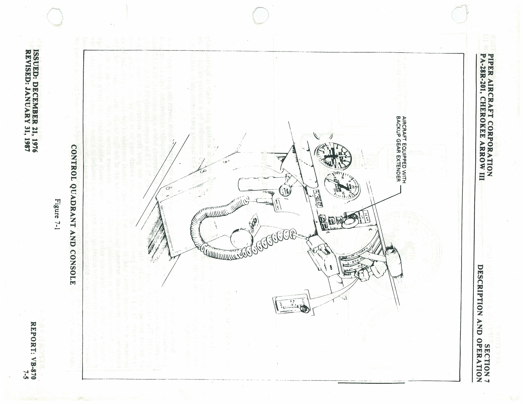
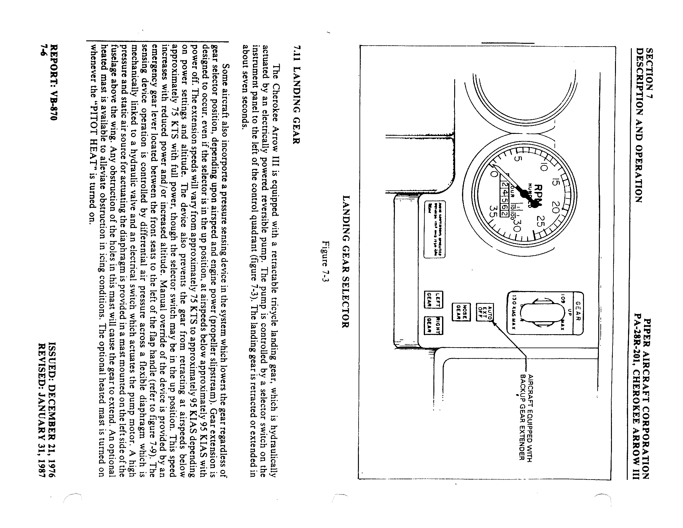
7.11 Landing Gear p. 172
The Cherokee Arrow III is equipped with a retractable tricycle landing gear, which is hydraulically actuated by an electrically powered reversible pump. The pump is controlled by a selector switch on the instrument panel to the left of the control quadrant (figure 7-3). The landing gear is retracted or extended in about seven seconds.
Some aircraft also incorporate a pressure sensing device in the system which lowers the gear regardless of gear selector position, depending upon airspeed and engine power (propeller slipstream). Gear extension is designed to occur, even if the selector is in the up position, at airspeeds below approximately 95 KIAS with power off. The extension speeds will vary from approximately 75 KTS to approximately 95 KIAS depending on power settings and altitude. The device also prevents the gear from retracting at airspeeds below approximately 75 KTS with full power, though the selector switch may be in the up position. This speed increases with reduced power and/or increased altitude. Manual override of the device is provided by an emergency gear lever located between the front seats to the left of the flap handle (refer to figure 7-9). The sensing device operation is controlled by differential air pressure across a flexible diaphragm which is mechanically linked to a hydraulic valve and an electrical switch which actuates the pump motor. A high pressure and static air source for actuating the diaphragm is provided in a mast mounted on the left side of the fuselage above the wing. Any obstruction of the holes in this mast will cause the gear to extend. An optional heated mast is available to alleviate obstruction in icing conditions. The optional heated mast is turned on whenever the "PITOT HEAT" is turned on.
p. 173 The emergency gear lever, when placed in the raised position, can be used to override the system, and gear position is then controlled by the selector switch regardless of airspeed/power combinations. The emergency gear lever is provided with a locking device which may be used to lock the override lever in the up position. The lock is located on the left side panel of the console below the level of the manual override lever. To lock the override lever in the up position, raise the override lever to the full up position and push the lock pin in. A yellow warning light located below the gear selector switch (figure 7-3) flashes to warn the pilot that the automatic gear lowering system is disabled. The lock is spring-loaded to the off position to aid disengagement. To disengage the lock raise the override lever and release. The lever will return to its normal position and the yellow flashing light will extinguish. The lever must also be locked in the raised (up) position when gear-up stalls are practiced.
The emergency gear lever, when used for emergency extension of the gear, manually releases hydraulic pressure to permit the gear to free-fall with spring assistance on the nose gear. The lever must be held in the downward position for emergency extension.
Gear down and locked positions are indicated by three green lights located below the selector, and a red "Warning Gear Unsafe" light is located at the top of the panel. An all lights out condition indicates the gear is up. The landing gear should not be retracted above a speed of 107 KIAS and should not be extended above a speed of 129 KIAS.
The main landing gear uses 6.00 x 6 wheels. The main gear incorporate brake drums and single disc hydraulic brake assemblies. The nose wheel carries a 5.00 x 5 four ply tire and the main gear use 6.00 x 6 six ply tires. All three tires are tube type.
A micro switch in the throttle quadrant activates a warning horn and red "Warning Gear Unsafe" light under the following conditions:
- Gear up and power reduced below approximately 14 inches of manifold pressure.
- On aircraft equipped with the backup gear extender, if the system has extended the landing gear and the gear extender is "UP," with the power reduced below approximately 14 inches of manifold pressure.
- Gear selector switch "UP" while on the ground and throttle in retarded position.
On aircraft which are NOT equipped with the backup gear extender, an additional switch is installed which activates the warning horn and light and flaps are extended beyond the approach position (10°) and the landing gear are not down and locked.
The gear warning horn emits a 90 Hz beeping sound in contrast to the stall warning horn which emits a continuous sound.
The nose gear is steerable through a 30 degree arc each side of center through the use of the rudder pedals. As the nose wheel retracts, the steering linkage disengages to reduce rudder pedal loads in flight. The nose wheel is equipped with a hydraulic shimmy dampener to reduce nose wheel shimmy. A bungee assembly is also included to reduce ground steering effort and to dampen shocks and bumps during taxiing.
The oleo struts are of the air-oil type, with normal extension being 2.75 + / - 0.25 inches for the nose gear and 2.5 + / - 0.25 inches for the main gear under normal static load (empty weight of airplane plus full fuel and oil).
The standard brake system includes toe brakes on the left and right set of rudder pedals and a hand brake located below and near the center of the instrument panel. The toe brakes and the hand brake have individual brake cylinders, but all cylinders use a common reservoir. The parking brake is incorporated in the lever brake and is operated by pulling back on the lever and depressing the knob attached to the top of the handle. To release the parking brake, pull back on the brake lever; then allow the handle to swing forward.
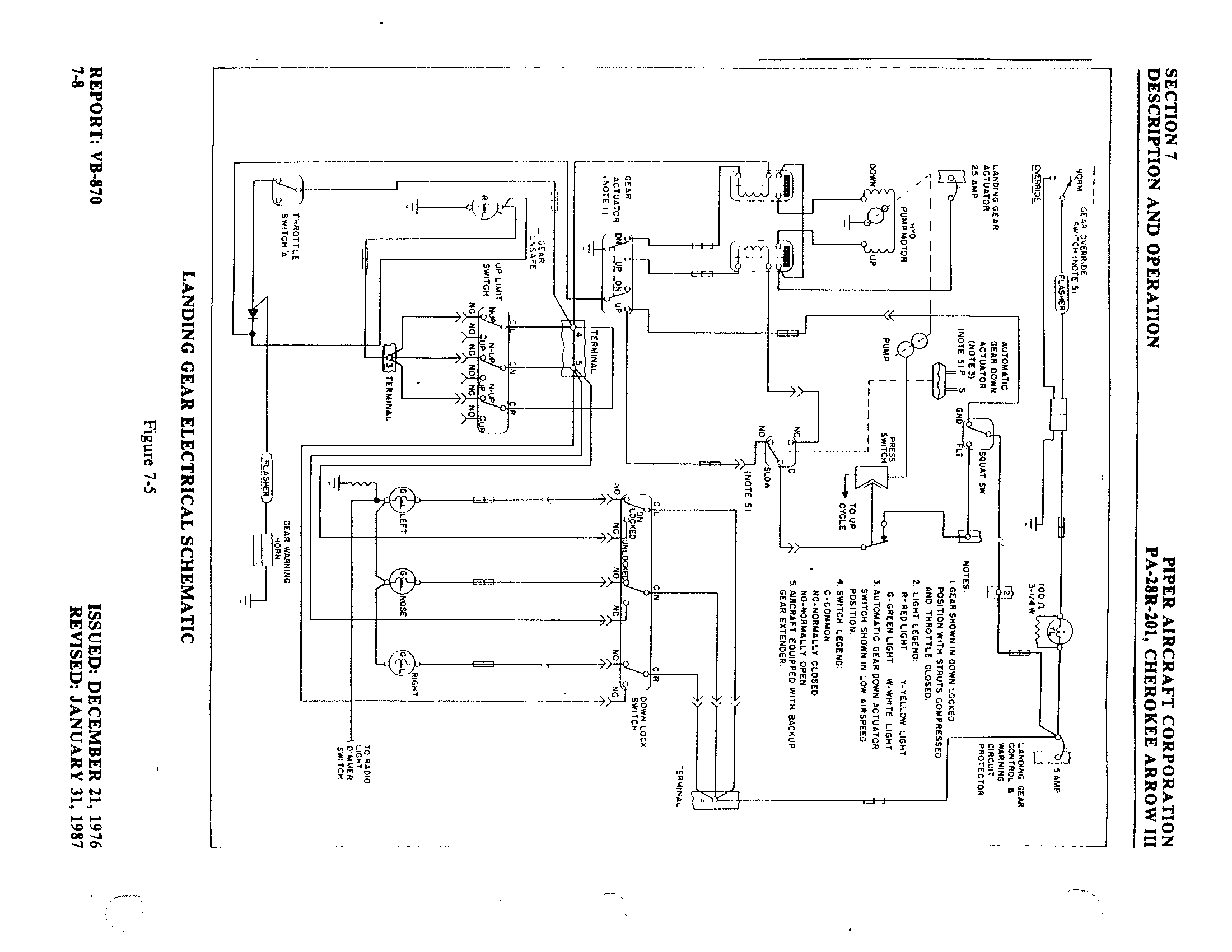
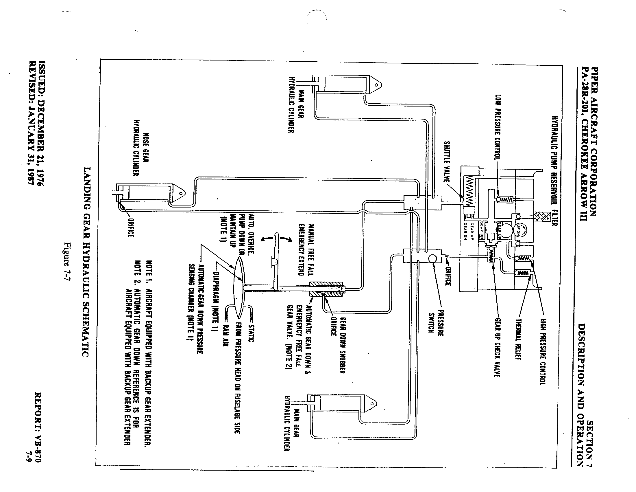
- Note 1. Aircraft equipped with Backup Gear Extender.
- Note 2. Automatic Gear Down reference is for aircraft equipped with Backup Gear Extender.
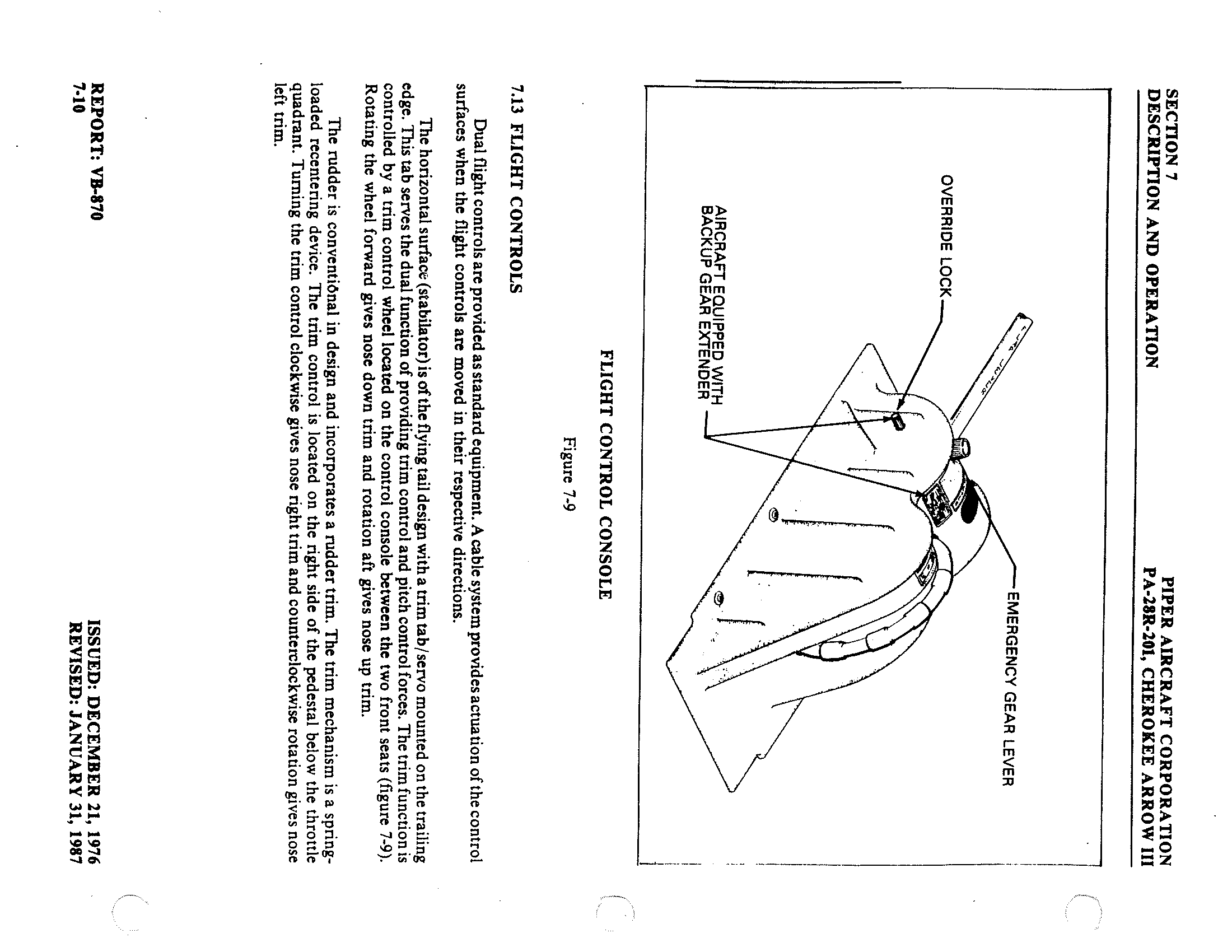
7.13 Flight Controls p. 176
Dual flight controls are provided as standard equipment. A cable system provides actuation of the control surfaces when the flight controls are moved in their respective directions.
The horizontal surface (stabilator) is of the flying tail design with a trim tab/servo mounted on the trailing edge. This tab serves the dual function of providing trim control and pitch control forces. The trim function is controlled by a trim control wheel located on the control console between the two front seats (figure 7-9). Rotating the wheel forward gives nose down trim and rotation aft gives nose up trim.
The rudder is conventional in design and incorporates a rudder trim. The trim mechanism is a spring-loaded recentering device. The trim control is located on the right side of the pedestal below the throttle quadrant. Turning the trim control clockwise gives nose right trim and counterclockwise rotation gives nose left trim.
p. 177 Manually controlled flaps are provided. They are extended by a control cable and are spring-loaded to the retracted (up) position. The control is located between the two front seats on the control console. To extend the flaps pull the handle up to the desired flap setting of 10, 25 or 40 degrees. To retract, depress the button on the end of the handle and lower the control.
When extending or retracting flaps, there is a pitch change in the aircraft. This pitch change can be corrected either by stabilator trim or increased control wheel force. When the flaps are in the retracted position the right flap, provided with a over-center lock mechanism, acts as a step.
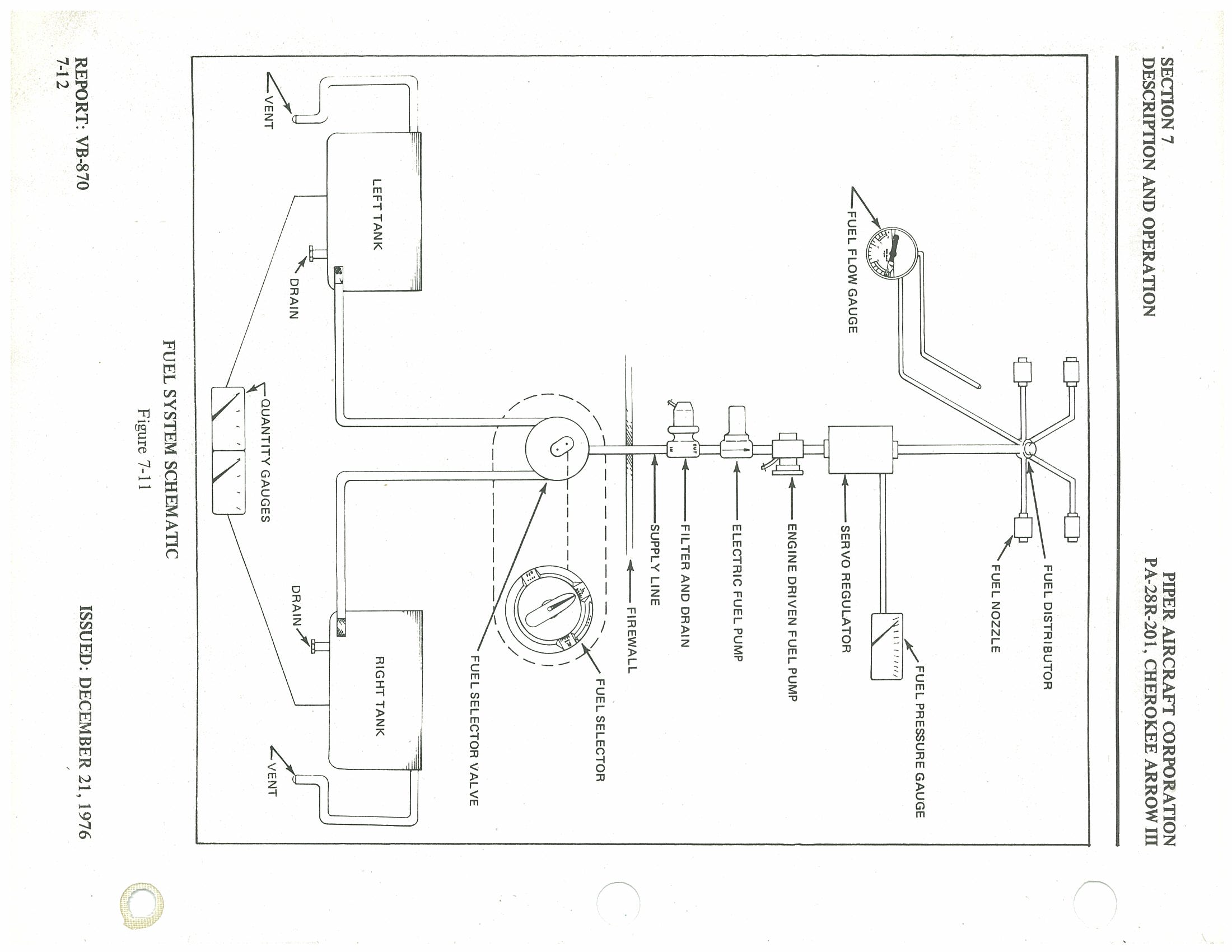
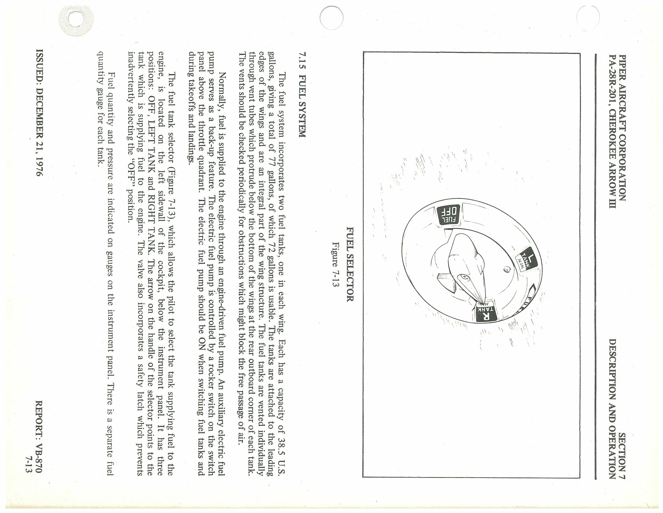
7.15 Fuel System p. 179
The fuel system incorporates two fuel tanks, one in each wing. Each has a capacity of 38.5 U.S. gallons, giving a total of 77 gallons, of which 72 gallons is usable. The tanks are attached to the leading edges of the wings and are an integral part of the wing structure. The fuel tanks are vented individually through vent tubes which protrude below the bottom of the wings at the rear outboard corner of each tank. The vents should be checked periodically for obstructions which might block the free passage of air.
Normally, fuel is supplied to the engine through an engine-driven fuel pump. An auxiliary electric fuel pump serves as a back-up feature. The electric fuel pump is controlled by a rocker switch on the switch panel above the throttle quadrant. The electric fuel pump should be ON when switching fuel tanks and during takeoffs and landings.
The fuel tank selector (Figure 7-13), which allows the pilot to select the tank supplying fuel to the engine, is located on the left sidewall of the cockpit, below the instrument panel. It has three positions: OFF, LEFT TANK and RIGHT TANK. The arrow on the handle of the selector points to the tank which is supplying fuel to the engine. The valve also incorporates a safety latch which prevents inadvertently selecting the "OFF" position.
Fuel quantity and pressure are indicated on gauges on the instrument panel. There is a separate fuel quantity gauge for each tank.
p. 180Each fuel tank has an individual quick drain located at the bottom inboard rear corner (see Figure 8-3). These drains are opened by insertion of the probe in the fuel sampler container into the drain. The fuel strainer incorporates a drain which protrudes from the cowling at the lower left front corner of the firewall. All three drains should be drained before flights and the drained fuel checked for contaminants.
7.17 Electrical System p. 181
The electrical system is very simple and functional. All switches are grouped in a switch panel above the power quadrant. On the lower right side of the instrument panel is the circuit breaker panel, with each breaker clearly marked to show what circuit it protects. Also, circuit provisions are made to handle a complete complement of communication and navigational equipment.
Standard electrical accessories include alternator, starter, electric fuel pump, stall warning indicator, ammeter, and annunciator panel.
The annunciator panel includes alternator and low oil pressure indicator lights. When the optional gyro system is installed, the annunciator panel also includes a low vacuum indicator light. The annunciator panel lights are provided only as a warning to the pilot that a system may not be operating properly, and that he should check and monitor the applicable system gauge to determine when or if any necessary action is required.
Optional electrical accessories include navigation, anti-collision, landing, instrument and cabin dome lights. Navigation and radio lights are controlled by a rheostat switch on the left side of the switch panel. The instrument panel lights are controlled by a rheostat switch on the right side of the panel.
The anti-collision and landing lights are controlled by rocker switches on the switch panel. Circuits will handle a full complement of communications and navigational equipment.
The master switch, also located in the switch panel, is a split rocker switch. One side of the switch is the battery side ("BAT") and the other is the alternator side ("ALT"). Henceforth, "master switch," used in this manual, shall mean both "BAT" and "ALT" switches. The "ALT" switch is provided for an emergency and its function is covered under "Alternator Failure" in the Emergency section of the handbook.
The primary electrical power source is a 14-volt, 60 amp alternator, which is protected by a voltage regulator and an overvoltage relay. The alternator provides full electrical power output even at low engine RPM. This provides improved radio and electrical equipment operation and increases battery life by reducing battery load.
Secondary power is provided by a 12-volt, 25 ampere hour battery.
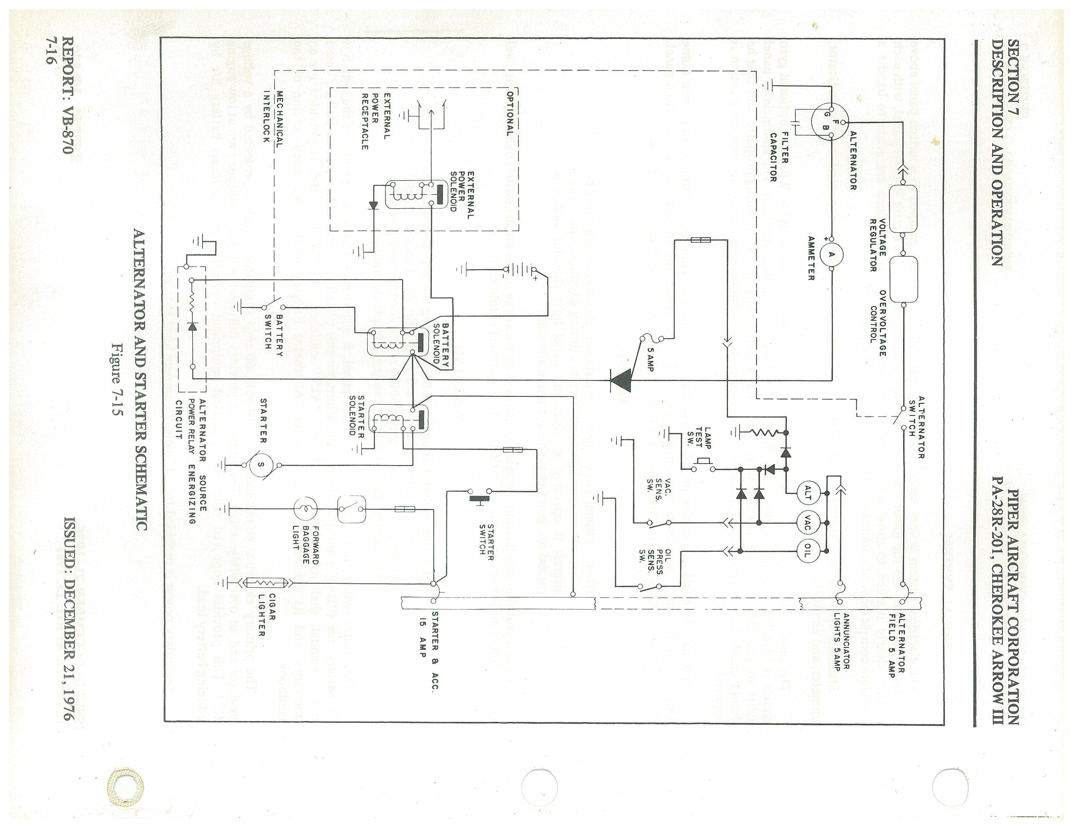
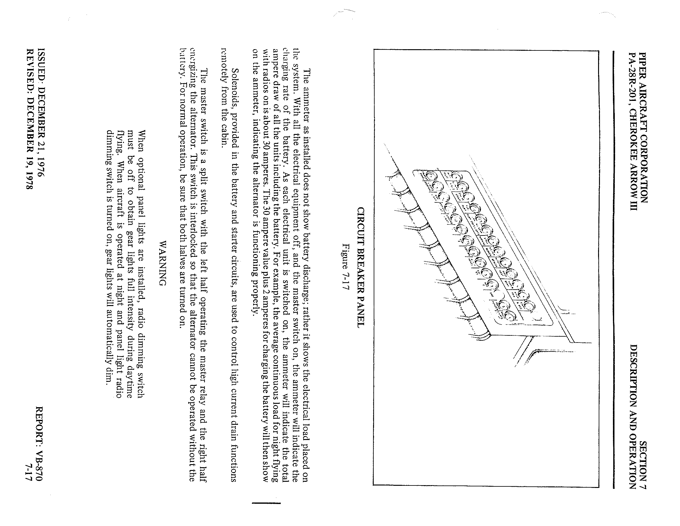
p. 183
The ammeter as installed does not show battery discharge; rather it shows the electrical load placed on the system. With all the electrical equipment off, and the master switch on, the ammeter will indicate the charging rate of the battery. As each electrical unit is switched on, the ammeter will indicate the total ampere draw of all the units including the battery. For example, the average continuous load for night flying with radios on is about 30 amperes. The 30 ampere value plus 2 amperes for charging the battery will then show on the ammeter, indicating the alternator is functioning properly.
Solenoids, provided in the battery and starter circuits, are used to control high current drain functions remotely from the cabin.
The master switch is a split switch with the left half operating the master relay and the right half energizing the alternator. This switch is interlocked so that the alternator cannot be operated without the battery. For normal operation, be sure that both halves are turned on.
7.19 Vacuum System p. 184
The vacuum system is designed to operate the air driven gyro instruments. This includes the directional and attitude gyros when installed. The system consists of an engine driven vacuum pump, a vacuum regulator, a filter and the necessary plumbing.
The vacuum pump is a dry type pump which eliminates the need for an air/oil separator and its plumbing. A shear drive protects the engine from damage. If the drive shears the gyros will become inoperative.
The vacuum gauge, mounted on the right instrument panel to the right of the radios, (refer to Figure 7-21) provides valuable information to the pilot about the operation of the vacuum system. A decrease in pressure in a system that has remained constant over an extended period, may indicate a dirty filter, dirty screens, possibly a sticking vacuum regulator or leak in system (a low vacuum indicator light is provided in the annunciator panel). Zero pressure would indicate a sheared pump drive, defective pump, possibly a defective gauge or collapsed line. In the event of any gauge variation from the norm, the pilot should have a mechanic check the system to prevent possible damage to the system components or eventual failure of the system.
A vacuum regulator is provided in the system to protect the gyros. The valve is set so the normal vacuum reads 4.8 to 5.2 inches of mercury, a setting which provides sufficient vacuum to operate all the gyros at their rated RPM. Higher settings will damage the gyros and with a low setting the gyros will be unreliable. The regulator is located behind the instrument panel.
7.21 Pitot-Static System
The system supplies both pitot and static pressure for the airspeed indicator, altimeter and vertical speed indicator (when installed).
Pitot pressure is picked up by the pitot head on the underside of the left wing. An optional heated pitot head, which alleviates problems with icing or heavy rain, is available. The switch for pitot heat is located on the switch panel.
Static pressure is sensed by static buttons on each side of the aft fuselage. Push-button type pitot and static drains are located on the lower left sidewall of the cockpit.
An alternate static source is available as optional equipment. The control valve is located below the left side of the instrument panel. When the valve is set in the alternate position, the altimeter, vertical speed indicator and airspeed indicator will be using cabin air for static pressure. The storm window and cabin vents must be closed and the cabin heater and defroster must be on during alternate static source operation. The altimeter error is less than 50 feet unless otherwise placarded.
To prevent bugs and water entering the pitot pressure hole when the airplane is parked, a cover should be placed over the pitot head. A partially or completely blocked pitot head will give erratic or zero readings on the instruments.
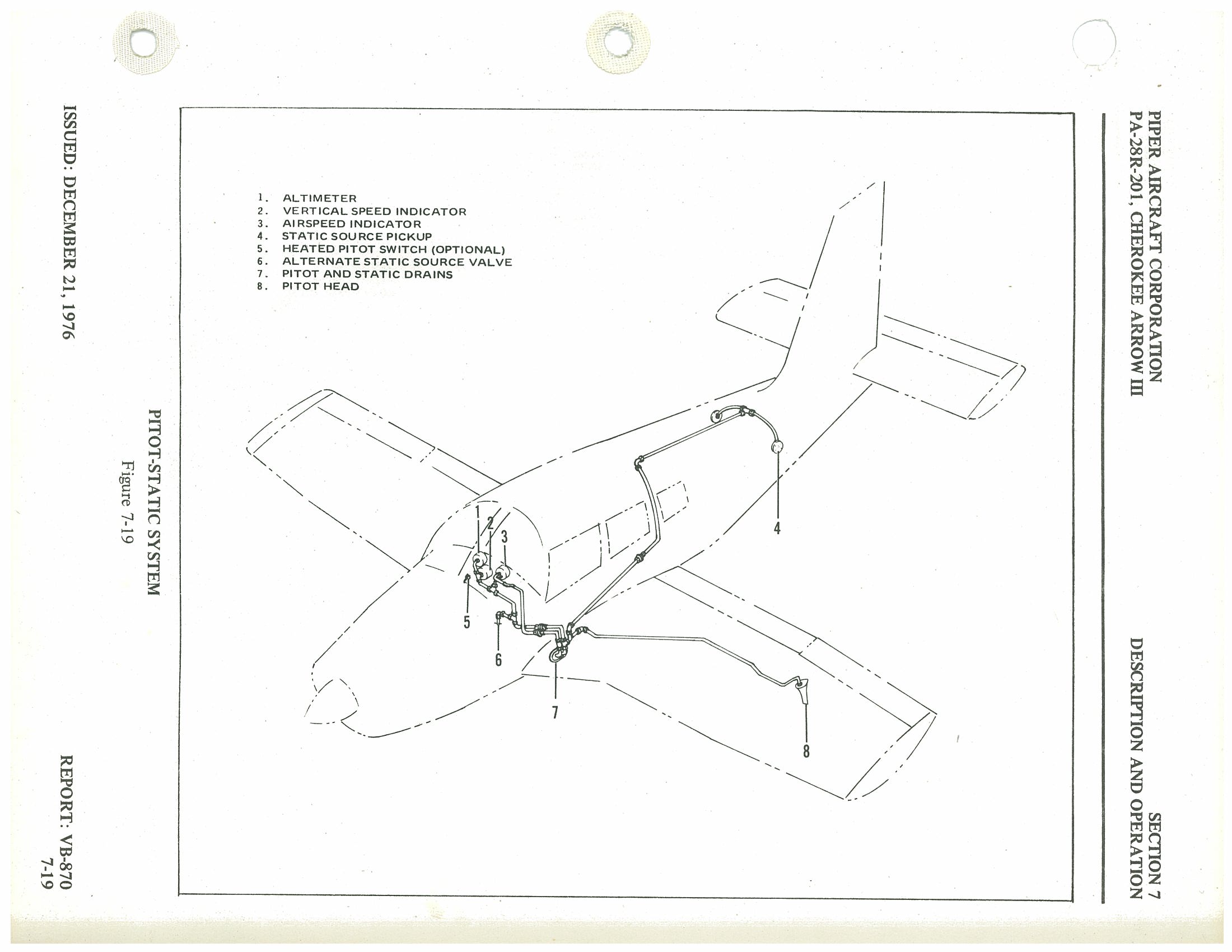
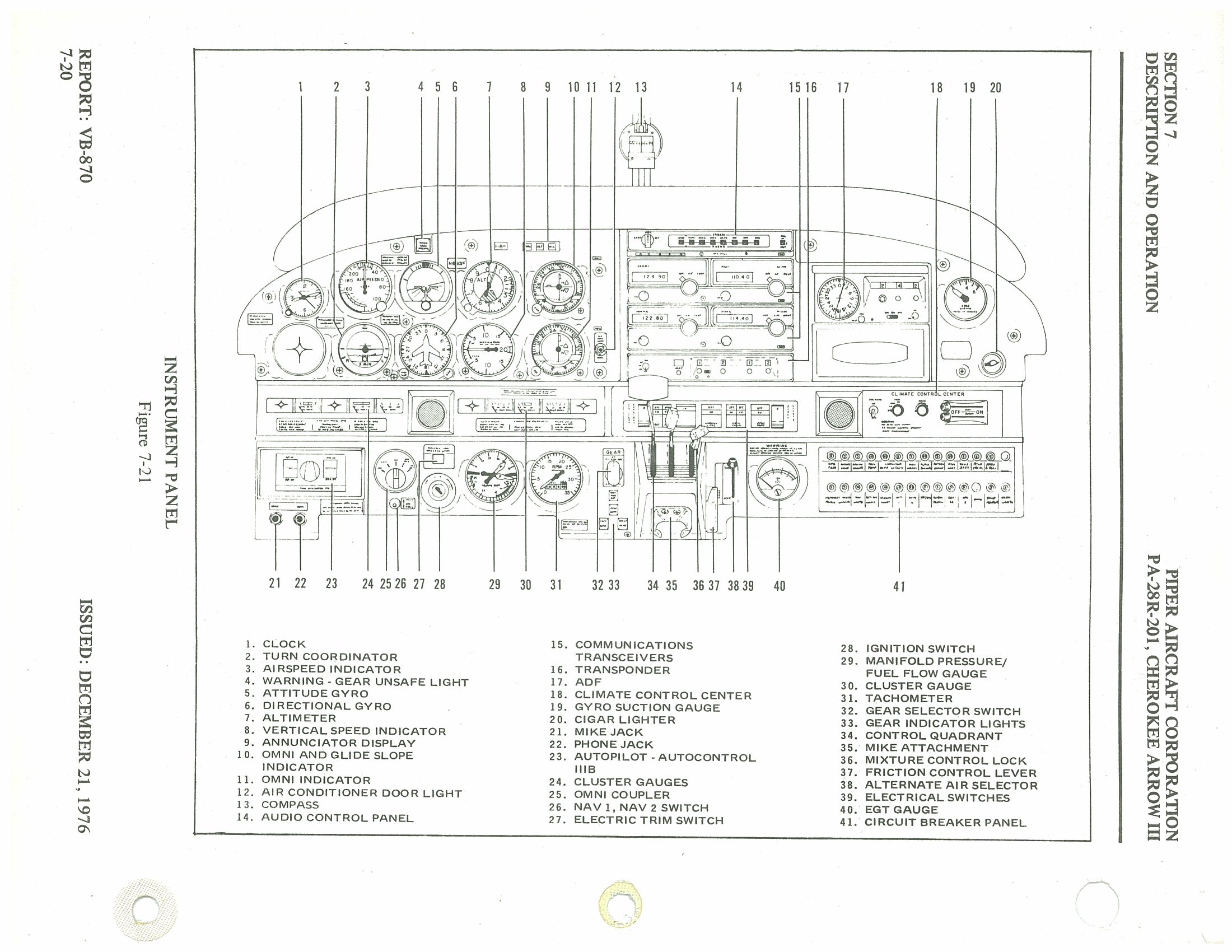
7.23 Instrument Panel p. 187
The instrument panel of the Cherokee Arrow III is designed to accommodate the customary advanced flight instruments and the normally required power plant instruments. The artificial horizon and directional gyro are vacuum operated and are located in the center of the left hand instrument panel. The vacuum gauge is located on the right hand instrument panel. The turn indicator, on the left side, is electrically operated.
The radios are located in the center section of the panel, and the circuit breakers are in the lower right corner of the panel.
An annunciator panel is mounted in the upper instrument panel to warn the pilot of a possible malfunction in the alternator, oil pressure, or vacuum systems.
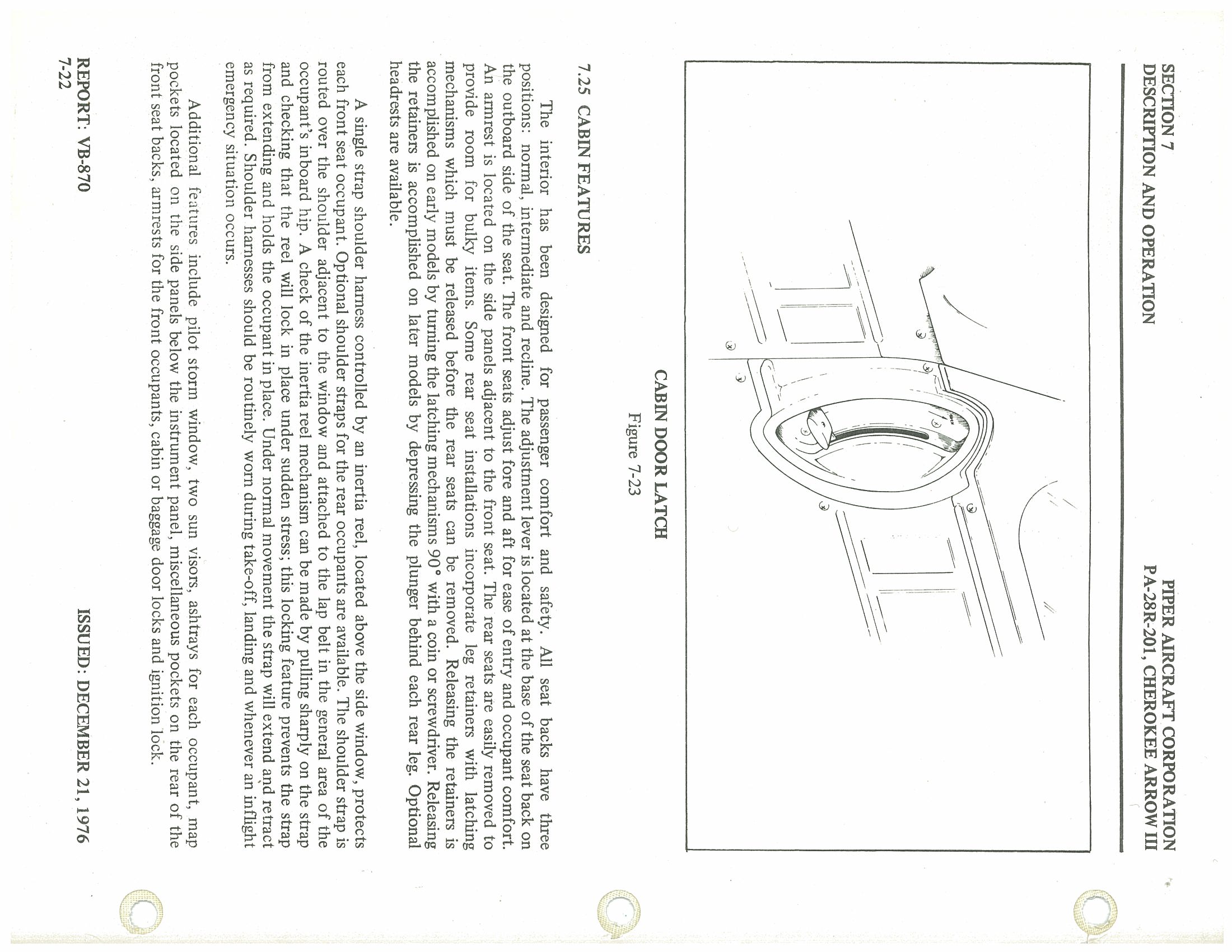
7.25 Cabin Features p. 188
The interior has been designed for passenger comfort and safety. All seat backs have three positions: normal, intermediate and recline. The adjustment lever is located at the base of the seat back on the outboard side of the seat. The front seats adjust fore and aft for ease of entry and occupant comfort. An armrest is located on the side panels adjacent to the front seat. The rear seats are easily removed to provide room for bulky items. Some rear seat installations incorporate leg retainers with latching mechanisms which must be released before the rear seats can be removed. Releasing the retainers is accomplished on early models by turning the latching mechanisms 90° with a coin or screwdriver. Releasing the retainers is accomplished on later models by depressing the plunger behind each rear leg. Optional headrests are available.
A single strap shoulder harness controlled by an inertia reel, located above the side window, protects each front seat occupant. Optional shoulder straps for the rear occupants are available. The shoulder strap is routed over the shoulder adjacent to the window and attached to the lap belt in the general area of the occupant's inboard hip. A check of the inertia reel mechanism can be made by pulling sharply on the strap and checking that the reel will lock in place under sudden stress; this locking feature prevents the strap from extending and holds the occupant in place. Under normal movement the strap will extend and retract as required. Shoulder harnesses should be routinely worn during take-off, landing and whenever an inflight emergency situation occurs.
Additional features include pilot storm window, two sun visors, ashtrays for each occupant, map pockets located on the side panels below the instrument panel, miscellaneous pockets on the rear of the front seat backs, armrests for the front occupants, cabin or baggage door locks and ignition lock.
p. 189 The cabin door is double latched. To close the cabin door, hold the door closed with the armrest while moving the side door latch to the "LATCHED" position. Then engage the top latch. Both latches must be secured before flight.
7.27 Baggage Area
The airplane has a 24 cubic foot aft baggage compartment located behind the rear seats and accessible through the cargo door on the aft side of the fuselage or from inside the cabin. Maximum capacity is 200 pounds. Tie down straps are provided and should be used at all times.
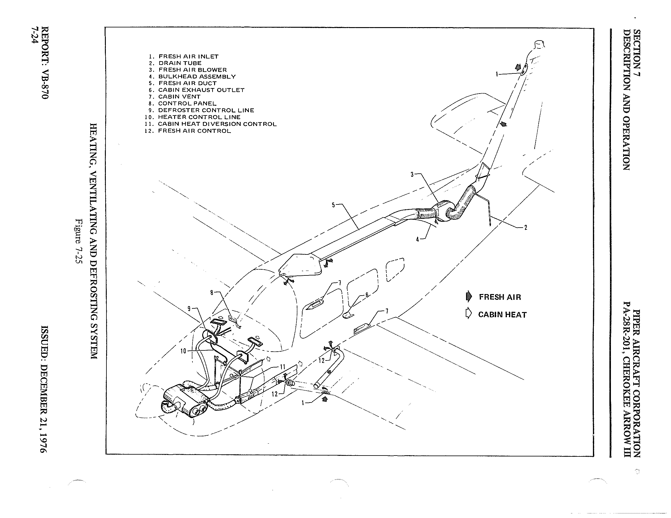
p. 190 The heating, ventilating and defrosting system diagram identifies the following components:
- 1. Fresh Air Inlet
- 2. Drain Tube
- 3. Fresh Air Blower
- 4. Fresh Air Duct Assembly
- 5. Cabin Exhaust Outlet
- 6. Fresh Air Duct
- 7. Cabin Vent
- 8. Control Panel
- 9. Defroster Control Line
- 10. Heater Control Line
- 11. Cabin Heat Diversion Control
- 12. Fresh Air Control
7.29 Heating and Ventilating System p. 191
The heating system is designed to provide maximum comfort for the occupants during winter and cool weather flights. The system includes a heat shroud, heat ducts, defroster outlets, heat and defroster controls.
An opening in the front of the lower cowl admits ram air to the heater shroud and then the air is ducted to the heater shut-offs on the right and left side of the firewall. When the shut-offs are opened the heated air then enters the heat ducts located along each side of the center console. Outlets in the heat duct are located at each seat location. Airflow to the rear seats can be regulated by controls in the heat ducts located between the front seats. The temperature of the cabin is regulated by the heater control located on the right side of the instrument panel.
Defrosting is accomplished by heat outlets located on the right and left side of the cowl cover. Heated air is ducted directly to defroster shut-off valves at the firewall, then to the defroster outlets. The airflow is regulated by a defroster control located below the heat control.
To aid air distribution, the cabin air is exhausted overboard by an outlet located on the bottom of the fuselage. Cabin exhaust outlets are located below and outboard of the rear seats. The above features are removed when air conditioning is installed.
Optional individual overhead fresh air outlets supply fresh air from an air inlet located on the tip of the vertical fin. The air is directed to a plenum chamber at the base of the fin, then ducted to the individual outlets. For individual comfort, the amount and direction of air can be regulated to control the amount of air and direction of desired airflow. An optional blower is available which forces outside air through the overhead vents for ground use. The blower is operated by a "FAN" switch with 4 positions — "OFF," "LOW," "MED," or "HIGH."
7.31 Stall Warning
An approaching stall is indicated by a stall warning horn which is activated between five and ten knots above stall speed. Mild airframe buffeting and gentle pitching may also precede the stall. Stall speeds are shown on graphs in the Performance Section. The stall warning horn emits a continuous sound. The landing gear warning horn is different in that it emits a 90 cycle per minute beeping sound. The stall warning horn is activated by a lift detector installed on the leading edge of the left wing. During preflight, the stall warning system should be checked by turning the master switch "ON," lifting the detector and checking to determine if the horn is actuated.
7.33 Finish
All exterior surfaces are primed with etching primer and finished with acrylic lacquer. To keep the finish attractive looking, economy size spray cans of touch-up paint are available from Piper Dealers.
7.35 Air Conditioning* p. 192
The air conditioning system is a recirculating air system. The major components include an evaporator, a condenser, a compressor, a blower, switches and temperature controls.
The evaporator is located behind the left rear side of the baggage compartment. This cools the air used for the air conditioning system.
The condenser is mounted on a retractable scoop located on the bottom of the fuselage and to the rear of the baggage compartment area. The scoop extends when the air conditioner is ON and retracts to a flush position when the system is OFF.
The compressor is mounted on the forward right underside of the engine. It has an electric clutch which automatically engages or disengages the compressor to the belt drive system of the compressor.
Air from the baggage area is drawn through the evaporator by the blower and distributed through an overhead duct to individual outlets located adjacent to each occupant.
The switches and temperature control are located on the lower right side of the instrument panel in the climate control center panel. The temperature control regulates the temperature of the cabin. Turning the control clockwise increases cooling; counterclockwise decreases cooling.
The fan speed switch and the air conditioning ON-OFF switch are inboard of the temperature control. The fan can be operated independently of the air conditioning; however, the fan must be on for air conditioner operation. Turning either switch off will disengage the compressor clutch and retract the condenser door. Cooling air should be felt within one minute after the air conditioner is turned on.
The fan switch allows operation of the fan with the air conditioner turned OFF to aid in cabin air circulation. "LOW," "MED" or "HIGH" can be selected to direct a flow of air through the air conditioner outlets in the overhead duct. These outlets can be adjusted or turned off individually.
The condenser door light is located to the right of the engine instrument cluster in front of the pilot. The door light illuminates when the door is open and is off when the door is closed.
A circuit breaker on the circuit breaker panel protects the air conditioning electrical system.
Whenever the throttle is in the full forward position, it actuates a micro switch which disengages the compressor and retracts the scoop. This allows maximum power and maximum rate of climb. The fan continues to operate and the air will remain cool for about one minute. When the throttle is retarded approximately 1/4 inch, the clutch will engage, the scoop will extend, and the system will again supply cool, dry air.
*Optional equipment
7.37 Piper External Power* p. 193
An optional starting installation known as Piper External Power (PEP) is accessible through a receptacle located on the right side of the fuselage aft of the baggage compartment door. An external battery can be connected to the socket, thus allowing the operator to crank the engine without having to gain access to the airplane's battery.
7.39 Emergency Locator Transmitter*
The Emergency Locator Transmitter (ELT) when installed, is located in the aft portion of the fuselage just below the stabilator leading edge and is accessible through a plate on the right side of the fuselage. This plate is attached with three slotted-head nylon screws for ease of removal; these screws may be readily removed with a variety of common items such as a dime, a key, a knife blade, etc. If there are no tools available in an emergency the screw heads may be broken off by any means. The ELT is an emergency locator transmitter which meets the requirements of FAR 91.52. The unit operates on a self-contained battery.
The battery has a useful life of 10 years. However, to comply with FAA regulations it must be replaced after 5 years of shelf life or service life. The battery should also be replaced if the transmitter has been used in an emergency situation or if accumulated test time exceeds one hour. The replacement date is marked on the transmitter label.
On the unit itself is a three position selector switch placarded "OFF," "ARM" and "ON." The "ARM" position is provided to set the unit to the automatic position so that it will transmit only after impact and will continue to transmit until the battery is drained to depletion or until the switch is manually moved to the "OFF" position. The "ARM" position is selected when the transmitter is installed at the factory and the switch should remain in that position whenever the unit is installed in the airplane. The "ON" position is provided so the unit can be used as a portable transmitter or in the event the automatic feature was not triggered by impact or to periodically test the function of the transmitter.
Select the "OFF" position when changing the battery, when rearming the unit if it has been activated for any reason, or to discontinue transmission.
A pilot's remote switch, located on the left side panel, is provided to allow the transmitter to be controlled from inside the cabin. The pilot's remote switch is placarded "ON, AUTO/ARM and OFF/RESET." The switch is normally left in the "AUTO/ARM" position. To turn the transmitter off, move the switch momentarily to the "OFF/RESET" position. The aircraft master switch must be "ON" to turn the transmitter "OFF." To actuate the transmitter for tests or other reasons, move the switch upward to the "ON" position and leave it in that position as long as transmission is desired.
*Optional equipment
p. 194The unit is equipped with a portable antenna to allow the locator to be removed from the airplane in case of an emergency and used as a portable signal transmitter.
The locator should be checked during the ground check to make certain the unit has not been accidentally activated. Check by tuning a radio receiver to 121.5 MHz. If there is an oscillating sound, the locator may have been activated and should be turned off immediately. Reset to the "ARM" position and check again to insure against outside interference.
Section 9 — Supplements p. 195
| Paragraph/Supplement No. | Title | Page No. |
|---|---|---|
| 9.1 | General | 9-1 |
| 1 | Air Conditioning System Installation | 9-3 |
| 2 | AutoFlite II Autopilot Installation | 9-7 |
| 3 | AutoControl IIIB Autopilot Installation | 9-9 |
| 4 | Piper Electric Pitch Trim | 9-13 |
9.1 General p. 196
This section provides information in the form of Supplements which are necessary for efficient operation of the airplane when equipped with one or more of the various optional systems and equipment not provided with the standard airplane.
All of the Supplements provided by this section are "FAA Approved" and consecutively numbered as a permanent part of this Handbook. The information contained in each Supplement applies only when the related equipment is installed in the airplane.
Supplement 1 — Air Conditioning Installation p. 198
Section 1 — General
This supplement supplies information necessary for the efficient operation of the airplane when the optional air conditioning system is installed. The information contained within this supplement is to be used in conjunction with the complete handbook.
This supplement has been "FAA Approved" as a permanent part of this handbook and must remain in this handbook at all times when the optional air conditioning system is installed.
Section 2 — Limitations
- To insure maximum climb performance the air conditioner must be turned "OFF" manually prior to takeoff to disengage the compressor and retract the condenser door. Also the air conditioner must be turned "OFF" manually before the landing approach in preparation for a possible go-around.
-
Placards
In full view of the pilot, in the area of the air conditioner controls when the air conditioner is installed:In full view of the pilot, to the right of the engine gauges (condenser door light):"WARNING - AIR CONDITIONER MUST BE OFF TO INSURE NORMAL TAKEOFF CLIMB PERFORMANCE.""AIR COND DOOR OPEN"
Section 3 — Emergency Procedures
No changes to the basic Emergency Procedures provided by Section 3 of this Pilot's Operating Handbook are necessary for this supplement.
Section 4 — Normal Procedures p. 199
Prior to takeoff, the air conditioner should be checked for proper operation as follows:
- Check aircraft master switch "ON."
- Turn the air conditioner control switch to "ON" and the fan switch to one of the operating positions — the "AIR COND DOOR OPEN" warning light will turn on, thereby indicating proper air conditioner condenser door actuation.
- Turn the air conditioner control switch to "OFF" — the "AIR COND DOOR OPEN" warning light will go out, thereby indicating the air conditioner condenser door is in the up position.
- If the "AIR COND DOOR OPEN" light does not respond as specified above, an air conditioner system or indicator bulb malfunction is indicated and further investigation should be conducted prior to flight.
The above operational check may be performed during flight if an in flight failure is suspected.
The condenser door light is located to the right of the engine instrument cluster in front of the pilot. The door light illuminates when the door is open and is off when the door is closed.
Section 5 — Performance
Operation of the air conditioner will cause slight decreases in cruise speed and range. Power from the engine is required to run the compressor, and the condenser door, when extended, causes a slight increase in drag. When the air conditioner is turned off there is normally no measurable difference in climb, cruise or range performance of the airplane.
Although the cruise speed and range are only slightly affected by the air conditioner operation, these changes should be considered in preflight planning. To be conservative, the following figures assume that the compressor is operating continuously while the airplane is airborne. This will be the case only in extremely hot weather.
- The decrease in true airspeed is approximately 6 KTS at all power settings.
- The decrease in range may be as much as 40 nautical miles for the 72 gallon usable fuel capacity.
p. 200 The climb performance is not compromised measurably with the air conditioner operating since the compressor is declutched and the condenser door is retracted, both automatically, when a full throttle position is selected. When the full throttle position is not used or in the event of a malfunction which would cause the compressor to operate and the condenser door to be extended, a decrease in rate of climb of as much as 100 fpm can be expected. Should a malfunction occur which prevents condenser door retraction when the compressor is turned off, a decrease in rate of climb of as much as 50 fpm can be expected.
Supplement 2 — AutoFlite II Autopilot Installation p. 202
Section 1 — General
This supplement supplies information necessary for the operation of the airplane when the optional AutoFlite II Autopilot is installed. The information contained within this supplement is to be used in conjunction with the complete handbook.
This supplement has been "FAA Approved" as a permanent part of this handbook based on EDO-AIRE Mitchell STC SA3162SW-D and must remain in this handbook at all times when the optional AutoFlite II Autopilot is installed.
Section 2 — Limitations
- Autopilot operation prohibited above 175 KIAS. (Autopilot Vmo)
- Autopilot must be "OFF" for takeoff and landing.
Section 3 — Emergency Procedures
- In case of malfunction, depress disconnect switch on pilot's control wheel, or overpower autopilot at either control wheel.
- AutoFlite II master switch — OFF.
- In climb, cruise or descent configuration a malfunction with a 3 second delay in recovery initiation may result in 50° bank and 190 foot altitude loss. Maximum altitude loss measured at 175 KIAS in a descent.
- In approach configuration, coupled or uncoupled, a malfunction with a 1 second delay in recovery initiation may result in 18° bank and 20 foot altitude loss.
Section 4 — Normal Procedures
AutoFlite II Preflight Inspection
- AutoFlite II master switch — ON.
- Rotate turn command knob to left and right. Aircraft control wheels should rotate in corresponding directions.
- With AutoFlite II on, rotate aircraft control wheel to left and right. Only light forces should be required to override roll servo clutch.
- AutoFlite II master switch — OFF — rotate control wheel left and right to assure disengagement.
AutoFlite II In-Flight Procedure p. 203
-
Engagement
- Check turn command knob in center detent position.
- AutoFlite II master switch — ON.
-
Disengagement
- AutoFlite II master switch — OFF.
-
Heading Changes
- Move trim knob on instrument for drift correction from a constant heading.
- Move turn command knob for left or right banked turns. Rotation of knob to stop will yield an appropriate bank angle to obtain an approximate standard rate turn. Intermediate settings may be used for lesser turn rates.
-
OMNI Tracker
-
Turn command knob — move to center detent position and push IN to engage tracker. Aircraft will track desired radial established on NAV 1 (or as selected, if equipped with a NAV selector switch).
NOTE: Tracker must be engaged within 10° of being "on course," i.e. VOR course needle centered and aircraft heading within 10° of VOR course.
- Trim knob — push IN for high sensitivity. Use high sensitivity position for localizer tracking and as desired for OMNI tracking.
-
Turn command knob — move to center detent position and push IN to engage tracker. Aircraft will track desired radial established on NAV 1 (or as selected, if equipped with a NAV selector switch).
- Maintain directional trim during all autopilot operations.
Performance
No changes to the basic performance provided by Section 5 of this Pilot's Operating Handbook are necessary for this supplement.
Supplement 3 — Autocontrol IIIB Autopilot Installation p. 204
Section 1 — General
This supplement supplies information necessary for the operation of the airplane when the optional Piper AutoControl IIIB Autopilot is installed. The information contained within this supplement is to be used in conjunction with the complete handbook.
This supplement has been FAA Approved as a permanent part of this handbook based on EDO=AIRE Mitchell STC SA3161SW-D and must remain in this handbook at all times when the optional Piper AutoControl IIIB Autopilot is installed.
Section 2 — Limitations
- Autopilot operation prohibited above 175 KIAS. (Autopilot VMO)
- Autopilot must be OFF for takeoff and landing.
Section 3 — Emergency Procedures
- In an emergency the AutoControl IIIB can be disconnected by:
- Pushing the A/P ON-OFF rocker switch — OFF.
- The autopilot can be overpowered at either control wheel.
- An autopilot runaway, with a 3 second delay in the initiation of recovery while operating in climb, cruise or descending flight, could result in a 58° bank and 190 foot altitude loss. Maximum altitude loss measured at 175 KIAS in a descent.
- An autopilot runaway, with a 1 second delay in the initiation of recovery, during an approach operation, coupled or uncoupled, could result in an 18° bank and 20 foot altitude loss.
- Emergency operation with optional NSD 360 and NSD 360A (HSI) — Slaved and/or Non-Slaved:
NSD 360
- Appearance of HDG Flag:
- Check air supply gauge (vac or pressure) for adequate air supply (4 in. Hg. min.).
- Check compass circuit breaker.
- Observe display for proper operation.
- To disable heading card — pull circuit breaker and use magnetic compass for directional data.
NOTE: If heading card is not operational, autopilot should not be used.(Continued)
- Appearance of HDG Flag:
-
p. 205
- With card disabled:
- VOR and Glide Slope displays are still functional; use card set to rotate card to aircraft heading for correct picture.
- Localizer — left-right information still usable. Flag information is disabled — compare needle with No. 2 indicator for valid left-right needle operation.
- Slaving Failure (i.e. failure to self-correct for gyro drift):
- Check gyro slaving switch is set to No. 1 position.
- Check for HDG Flag.
- Check compass circuit breaker.
- Reset heading card while observing slaving meter.
- Select slaving amplifier No. 2 (gyro slaving switch is set to No. 2 position).
- Reset heading card while checking slaving meter.
- Switch to free gyro and periodically set card as unslaved gyro.
NSD 360A (Instrument with red-white striped NAV-HDG Flags)
- The emergency procedures for the NSD 360A remain identical to those listed for the NSD 360 (above), except that the presence of the NAV Flag on a localizer frequency invalidates the NAV left-right information. Usable navigation data will be indicated in both VOR and Localizer modes by the absence of the NAV Flag, whether the card is disabled or not.
- In the localizer mode the "TO-FROM" arrows may remain out of view, depending upon the design of the NAV converter used in the installation.
- With card disabled:
Section 4 — Normal Procedures
Preflight
- AUTOPILOT
- Place radio coupler in HDG mode (if installed) and place the A/P "ON-OFF" switch to the "ON" position to engage roll section. Rotate roll command knob left and right and observe that control wheel describes a corresponding left and right turn, then center knob.
- Set proper D.G. heading on D.G. and turn HDG bug to aircraft heading. Engage HDG mode rocker switch and rotate HDG bug right and left. Aircraft control wheel should turn same direction as bug. Grasp control wheel and manually override servo, both directions.
- RADIO COUPLER — (OPTIONAL)
- Tune and identify VOR or VOT station. Position radio coupler to OMNI mode. Engage autopilot "ON" and HDG switches. Set HDG bug to aircraft heading and rotate OBS to cause OMNI indicator needle to swing left and right slowly. Observe that control wheel rotates in direction of needle movement.
- Disengage A/P "ON-OFF" switch. Reset radio coupler control to HDG.
In-Flight
- Trim airplane (ball centered).
- Check air pressure or vacuum to ascertain that the directional gyro and attitude gyro are receiving sufficient air.
- p. 206 Roll Section:
- To engage, center roll knob, push A/P "ON-OFF" switch to "ON" position. To turn, rotate console roll knob in desired direction. (Maximum angle of bank should not exceed 30°.)
- For heading mode, set directional gyro with magnetic compass. Push directional gyro HDG knob in, rotate bug to aircraft heading. Push console heading rocker (HDG) switch to "ON" position. To select a new aircraft heading, push D.G. heading knob "IN" and rotate, in desired direction of turn, to the desired heading.
- Radio Coupling VOR-ILS with H.S.I. (Horizontal Situation Indicator) Type Instrument Display — (Optional)
- VOR Navigation
- Tune and identify VOR station. Select desired course by rotating CRS knob of H.S.I.
- Select OMNI mode on radio coupler.
- Select HDG mode on autopilot console to engage coupler. Aircraft will turn to a 45° intercept angle to intercept the selected VOR course. Intercept angle magnitude depends on radio needle off course magnitude; 100% needle deflection will result in 45° intercept with the intercept angle diminishing as the needle offset diminishes.
- NAV mode — NAV mode provides reduced VOR sensitivity for tracking weak, or noisy VOR signals. NAV mode should be selected after the aircraft is established on course.
- ILS-LOC Front Course
- Set inbound, front, localizer course on H.S.I.
- Select LOC-Normal on radio coupler to intercept and track inbound on localizer. Select LOC-REV to intercept and track outbound to the procedure turn area.
- Select HDG mode on autopilot console to engage coupler.
- ILS — Back Course
- Set inbound, front localizer course on H.S.I.
- Select LOC-REV on radio coupler to intercept and track inbound on the back localizer course. Select LOC-NORM to intercept and track outbound on the back course to the procedure turn area.
- Select HDG mode on autopilot console to engage coupler.
- VOR Navigation
- Radio Coupling — VOR-ILS with standard directional gyro. (Optional)
Radio coupler operation in conjunction with a standard directional gyro and VOR-LOC display differs from operation with an integrated display (H.S.I.) only in one respect. The HDG bug is used as the radio course datum and therefore must be set to match the desired VOR course as selected on the OBS.
- For VOR intercepts and tracking:
Select the desired VOR course and set the HDG bug to the same heading. Select OMNI mode on the coupler and HDG mode on the autopilot console.
- For ILS Front Course intercepts and tracking:
Tune the localizer frequency and place the HDG bug on the inbound, front course heading. Select LOC-NORM mode on the coupler and HDG mode on the autopilot console.
- For LOC Back Course intercepts and tracking:
Tune the localizer frequency and place the HDG bug on the inbound course heading to the airport. Select LOC-REV mode with coupler and HDG mode on the autopilot console.
- For VOR intercepts and tracking:
Section 5 – Performance p. 207
No changes to the basic performance provided by Section 5 of the Pilot's Operating Handbook are necessary for this supplement.
Supplement 4 — Piper Electric Pitch Trim p. 208
Section 1 – General
This supplement supplies information necessary for the operation of the airplane when the optional Piper Electric Pitch Trim is installed. The information contained within this supplement is to be used in conjunction with the complete handbook.
This supplement has been "FAA Approved" as a permanent part of this handbook and must remain in this handbook at all times when the optional Piper Electric Pitch Trim is installed.
Section 2 – Limitations
No changes of the basic limitations provided by Section 2 of this Pilot's Operating Handbook are necessary for this supplement.
Section 3 – Emergency Procedures
- In case of malfunction, PRESS disconnect switch located above the ignition switch.
- In case of malfunction, overpower the electric trim at either control wheel.
- Maximum altitude change with a 4 second delay in recovery initiation is 500 feet and occurs in the power approach and cruise configurations, and results in a 20° pitch change.
Section 4 – Normal Procedures
The electric trim system may be turned ON or OFF by a switch located above the ignition switch. The pitch trim may be changed when the electric trim system is turned on either by moving the manual pitch trim control wheel or by operating the trim control switch on the pilot's control yoke.
Section 5 – Performance
No changes to the basic performance provided by Section 5 of this Pilot's Operating Handbook are necessary for this supplement.
Section 10 — Safety Tips p. 210
10.1 General p. 211
This section provides safety tips of particular value in the operation of the Cherokee Arrow III.
10.3 Safety Tips
- Learn to trim for takeoff so that only a very light back pressure on the control wheel is required to lift the airplane off the ground.
- The best speed for takeoff is about 70 KIAS under normal conditions. Trying to pull the airplane off the ground at too low an airspeed decreases the controllability of the airplane in the event of engine failure.
- Flaps may be lowered at airspeeds up to 103 KIAS. To reduce flap operating loads, it is desirable to have the airplane at a slower speed before extending the flaps. The flap step will not support weight if the flaps are in any extended position. The flaps must be placed in the "UP" position before they will lock and support weight on the step.
- Before attempting to reset any circuit breaker, allow a two to five minute cooling off period.
- Before starting the engine, check that all radio switches, light switches and the pitot heat switch are in the off position so as not to create an overloaded condition when the starter is engaged.
- Strobe lights should not be operating when flying through overcast and clouds, since reflected light can produce spacial disorientation. Do not operate strobe lights in close proximity to ground.
- The rudder pedals are suspended from a torque tube which extends across the fuselage. The pilot should become familiar with the proper positioning of his feet on the rudder pedals so as to avoid interference with the torque tube when moving the rudder pedals or operating the toe brakes.
- In an effort to avoid accidents, pilots should obtain and study the safety related information made available in FAA publications such as regulations, advisory circulars, Aviation News, AIM and safety aids.
- Extreme running turning takeoffs should be avoided as fuel flow interruption may occur.
- Prolonged slips or skids which result in excess of 2000 ft. of altitude loss, or other radical or extreme maneuvers which could cause uncovering of the fuel outlet must be avoided as fuel flow interruption may occur when tank being used is not full.