
1973 Cessna 172M POH
Section I — Operating Check List p. 7
One of the first steps in obtaining the utmost performance, service, and flying enjoyment from your Cessna is to familiarize yourself with your aircraft's equipment, systems, and controls. This can best be done by reviewing this equipment while sitting in the aircraft. Those items whose function and operation are not obvious are covered in Section II.
Section I lists, in Pilot's Check List form, the steps necessary to operate your aircraft efficiently and safely. It is not a check list in its true form as it is considerably longer, but it does cover briefly all of the points that you should know for a typical flight. An abbreviated check list covering the "Before Take-Off" and "Before Landing" phases of aircraft operation is provided on a plastic card and normally stowed in the map compartment. This abbreviated check list is a convenient reference of key items to be rechecked immediately prior to taxiing into position for take-off and before entering the final approach for landing.
The flight and operational characteristics of your aircraft are normal in all respects. There are no "unconventional" characteristics or operations that need to be mastered. All controls respond in the normal way within the entire range of operation. All airspeeds mentioned in Sections I, II and III are indicated airspeeds. Corresponding calibrated airspeed may be obtained from the Airspeed Correction Table in Section VI.
Before Entering the Airplane
- Make an exterior inspection in accordance with figure 1-1.
Exterior Inspection p. 8
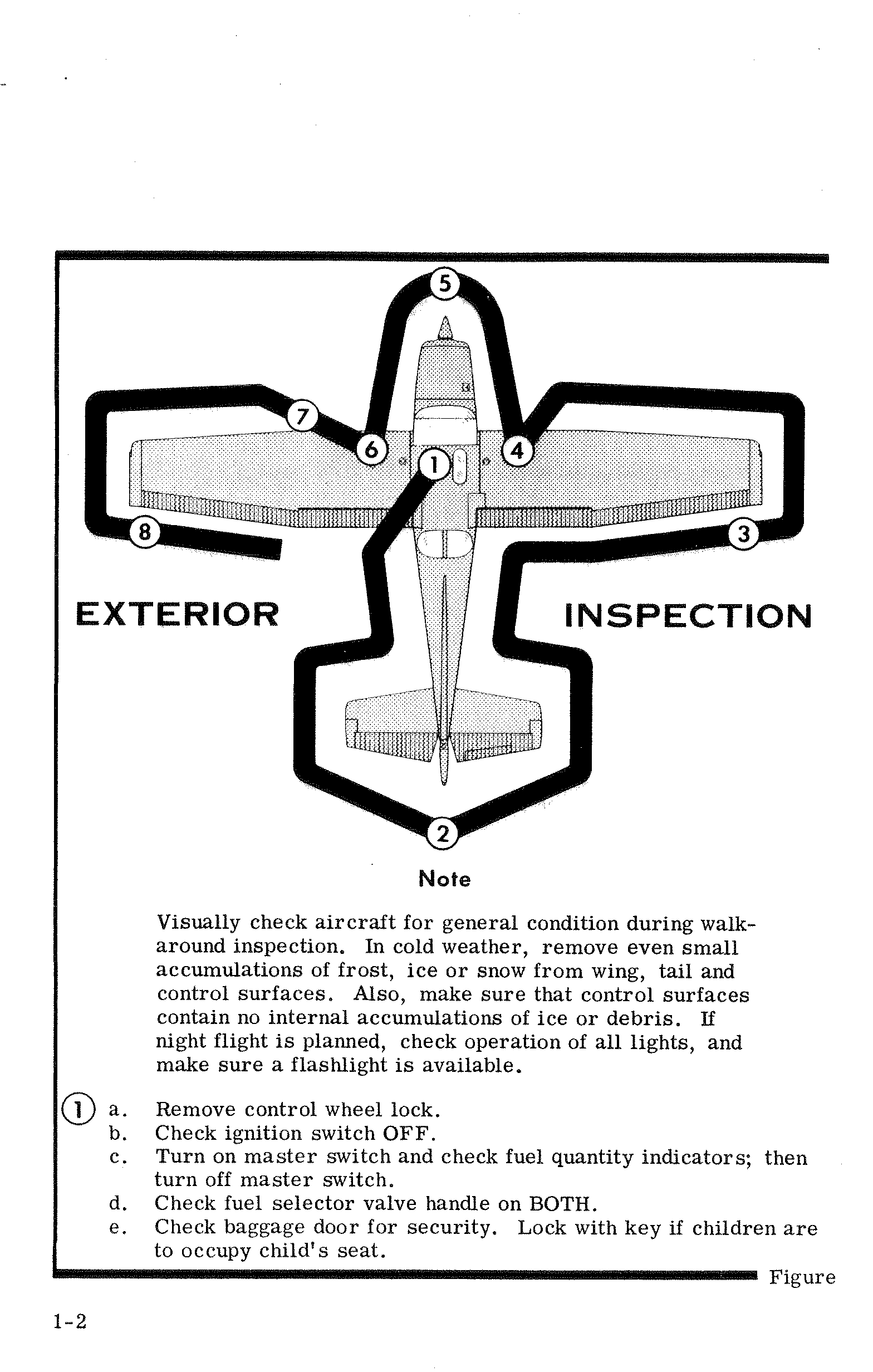
① Cabin
- a. Remove control wheel lock.
- b. Check ignition switch OFF.
- c. Turn on master switch and check fuel quantity indicators; then turn off master switch.
- d. Check fuel selector valve handle on BOTH.
- e. Check baggage door for security. Lock with key if children are to occupy child's seat.
② Empennage p. 9
- a. Remove rudder gust lock, if installed.
- b. Disconnect tail tie-down.
- c. Check control surfaces for freedom of movement and security.
③ Right Wing (Trailing Edge)
- a. Check aileron for freedom of movement and security.
④ Right Wing (Leading Edge / Landing Gear)
- a. Disconnect wing tie-down.
- b. Check main wheel tire for proper inflation.
- c. Visually check fuel quantity; then check fuel filler cap secure.
⑤ Nose / Engine
- a. Check oil level. Do not operate with less than six quarts. Fill to eight quarts for extended flights.
- b. Before first flight of day and after each refueling, pull out strainer drain knob for about four seconds to clear fuel strainer of possible water and sediment. Check strainer drain closed. If water is observed, there is a possibility that the fuel tank sumps contain water. Thus, the fuel tank sump drain plugs and fuel selector valve drain plug should be removed to check for the presence of water.
- c. Check propeller and spinner for nicks and security.
- d. Check landing light for condition and cleanliness.
- e. Check carburetor air filter for restrictions by dust or other foreign matter.
- f. Check nose wheel strut and tire for proper inflation.
- g. Disconnect tie-down rope.
- h. Inspect flight instrument static source opening on side of fuselage for stoppage (left side only).
⑥ Left Wing (Leading Edge / Landing Gear)
- a. Check main wheel tire for proper inflation.
- b. Visually check fuel quantity, then check fuel filler cap secure.
⑦ Left Wing (Leading Edge / Pitot)
- a. Remove pitot tube cover, if installed, and check pitot tube opening for stoppage.
- b. Check fuel tank vent opening for stoppage.
- c. Check stall warning vent opening for stoppage.
- d. Disconnect wing tie-down.
⑧ Left Wing (Trailing Edge)
- a. Check aileron for freedom of movement and security.
Before Starting the Engine p. 10
- Seats, Seat Belts and Shoulder Harnesses — Adjust and lock.
- Fuel Selector Valve — BOTH.
- Brakes — Test and set.
- Radios and Electrical Equipment — OFF.
Starting the Engine
- Mixture — Rich.
- Carburetor Heat — Cold.
- Primer — 2–6 strokes as required (none if engine is warm). Close and lock primer.
- Throttle — Open 1/8".
- Master Switch — ON.
- Propeller Area — Clear.
- Ignition Switch — START (release when engine starts).
- Oil Pressure — Check.
Before Take-Off
- Parking Brake — Set.
- Flight Controls — Check for free and correct movement.
- Fuel Selector Valve — BOTH.
- Elevator Trim Control Wheel — TAKE-OFF setting.
- Throttle Setting — 1700 RPM.
- Engine Instruments and Ammeter — Check.
- Suction Gage — Check (4.6 to 5.4 inches of mercury).
- Magnetos — Check (RPM drop should not exceed 125 RPM on either magneto or 50 RPM differential between magnetos).
- Carburetor Heat — Check operation.
- Flight Instruments and Radios — Set.
- Optional Autopilot or Wing Leveler — Off.
- Cabin Doors and Window — Closed and locked.
Take-Off
Normal Take-Off
- Wing Flaps — 0°.
- Carburetor Heat — Cold.
- Power — Full throttle. p. 11
- Elevator Control — Lift nose wheel at 60 MPH.
- Climb Speed — 75 to 85 MPH.
Maximum Performance Take-Off
- Wing Flaps — 0°.
- Carburetor Heat — Cold.
- Brakes — Apply.
- Power — Full throttle.
- Brakes — Release.
- Airplane Attitude — Slightly tail low.
- Climb Speed — 68 MPH until all obstacles are cleared.
Climb
- Airspeed — 80 to 90 MPH.
- Power — Full throttle.
- Mixture — Full rich (mixture may be leaned above 3000 feet).
Cruising
- Power — 2200 to 2700 RPM.
- Elevator Trim Control Wheel — Adjust.
- Mixture — Lean for maximum RPM.
Let-Down p. 12
- Mixture — Rich.
- Power — As desired.
- Carburetor Heat — As required to prevent carburetor icing.
Before Landing
- Fuel Selector Valve — BOTH.
- Mixture — Rich.
- Carburetor Heat — Apply full heat before closing throttle.
- Wing Flaps — As desired.
- Airspeed — 70 to 80 MPH (flaps up), 65 to 75 MPH (flaps down).
Balked Landing (Go-Around)
- Power — Full throttle.
- Carburetor Heat — Cold.
- Wing Flaps — Retract to 20°.
- Upon reaching an airspeed of approximately 65 MPH, retract flaps slowly.
Normal Landing
- Touchdown — Main wheels first.
- Landing Roll — Lower nose wheel gently.
- Braking — Minimum required.
After Landing
- Wing Flaps — Up.
- Carburetor Heat — Cold.
Securing Aircraft p. 13
- Parking Brake — Set.
- Radios and Electrical Equipment — OFF.
- Mixture — Idle cut-off (pulled full out).
- Ignition and Master Switch — OFF.
- Control Lock — Installed.
Section II — Description and Operating Details p. 14
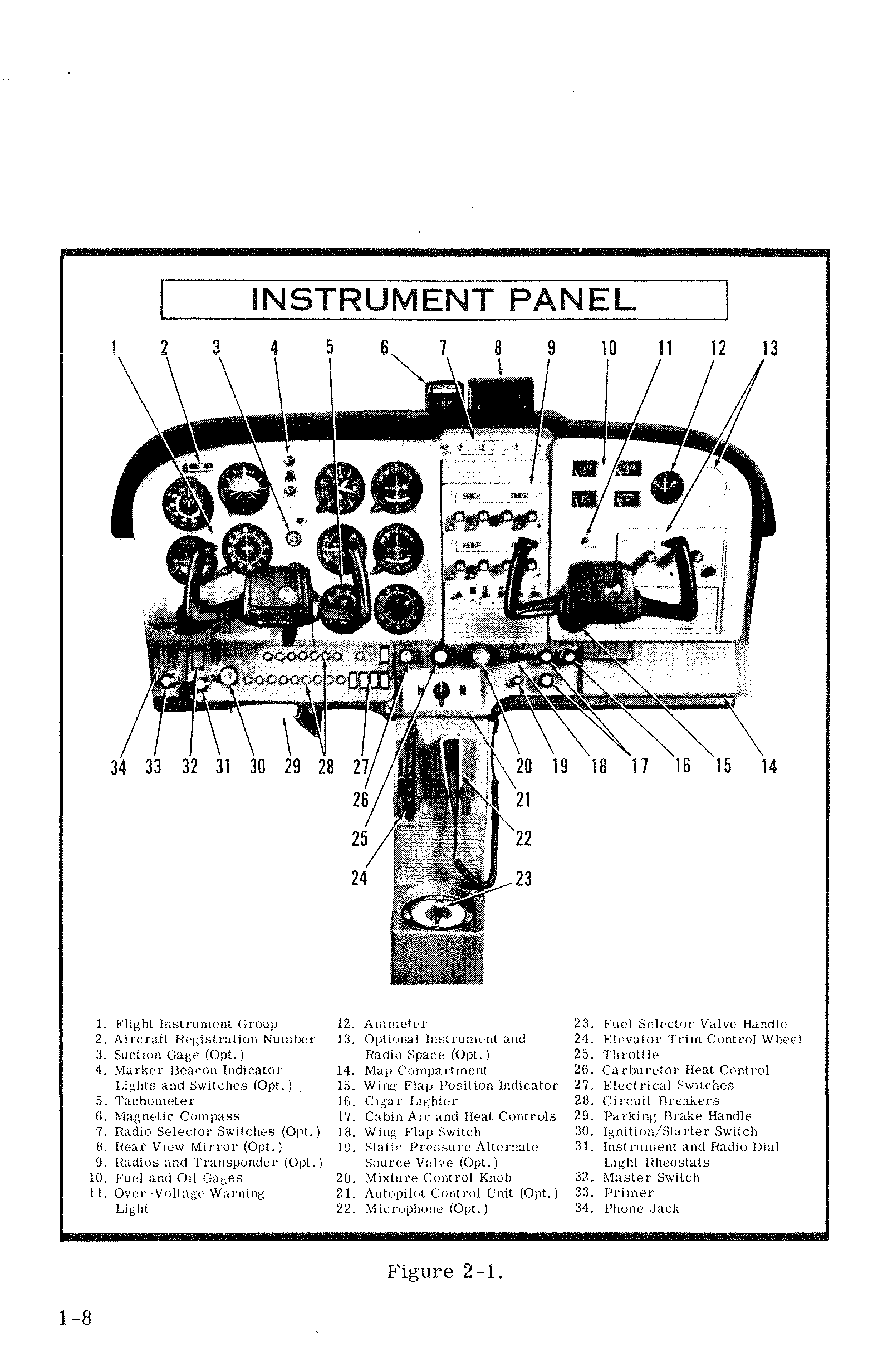
Instrument Panel Legend
| # | Item | # | Item | # | Item |
|---|---|---|---|---|---|
| 1 | Flight Instrument Group | 12 | Ammeter | 23 | Fuel Selector Valve Handle |
| 2 | Aircraft Registration Number | 13 | Optional Instrument and Radio Space (Opt.) | 24 | Elevator Trim Control Wheel |
| 3 | Suction Gage (Opt.) | 14 | Map Compartment | 25 | Throttle |
| 4 | Marker Beacon Indicator Lights and Switches (Opt.) | 15 | Wing Flap Position Indicator | 26 | Carburetor Heat Control |
| 5 | Tachometer | 16 | Cigar Lighter | 27 | Electrical Switches |
| 6 | Magnetic Compass | 17 | Cabin Air and Heat Controls | 28 | Circuit Breakers |
| 7 | Radio Selector Switches (Opt.) | 18 | Wing Flap Switch | 29 | Parking Brake Handle |
| 8 | Rear View Mirror (Opt.) | 19 | Static Pressure Alternate Source Valve (Opt.) | 30 | Ignition/Starter Switch |
| 9 | Radios and Transponder (Opt.) | 20 | Mixture Control Knob | 31 | Instrument and Radio Dial Light Rheostats |
| 10 | Fuel and Oil Gages | 21 | Autopilot Control Unit (Opt.) | 32 | Master Switch |
| 11 | Over-Voltage Warning Light | 22 | Microphone (Opt.) | 33 | Primer |
| 34 | Phone Jack |
p. 15
The following paragraphs describe the systems and equipment whose function and operation is not obvious when sitting in the aircraft. This section also covers in somewhat greater detail some of the items listed in Check List form in Section I that require further explanation.
Fuel System
Fuel is supplied to the engine from two tanks, one in each wing. With the fuel selector valve on BOTH, the total usable fuel for all flight conditions is 38 gallons for the standard tanks and 48 gallons for the optional long range tanks.
Fuel from each wing tank flows by gravity to a selector valve. Depending upon the setting of the selector valve, fuel from the left, right, or both tanks flows through a fuel strainer and carburetor to the engine induction system.
The fuel selector valve should be in the BOTH position for take-off, climb, landing, and maneuvers that involve prolonged slips or skids. Operation from either LEFT or RIGHT tank is reserved for cruising flight.
Continued on next page
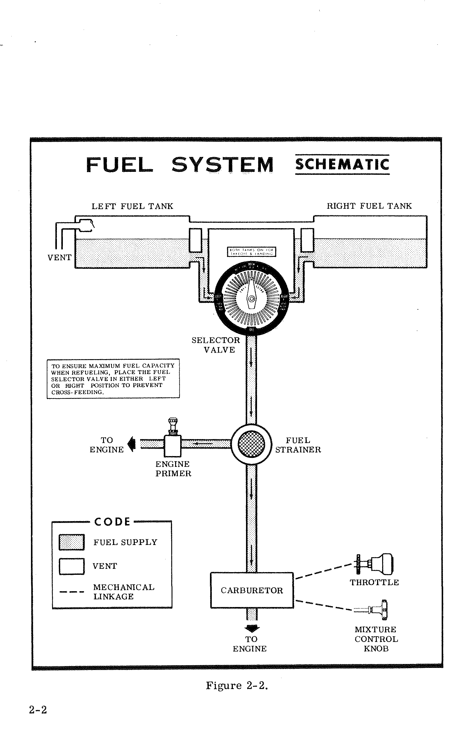
tank may occur if the wings are not maintained exactly level. Resulting wing heaviness can be alleviated gradually by turning the selector valve handle to the tank in the "heavy" wing.
For fuel system servicing information, refer to Lubrication and Servicing Procedures in Section V.
Electrical System
Electrical energy is supplied by a 14-volt, direct-current system powered by an engine-driven alternator (see figure 2-3). A 12-volt battery is located on the left-hand forward portion of the firewall. Power is supplied to all electrical circuits through a split bus bar, one side containing electronic systems and the other side having general electrical systems. Both sides of the bus are on at all times except when either an external power source is connected or the ignition/starter switch is turned on; then a power contactor is automatically activated to open the circuit to the electronic bus. Isolating the electronic circuits in this manner prevents harmful transient voltages from damaging the transistors in the electronic equipment.
Master Switch
The master switch is a split-rocker type switch labeled MASTER, and is ON in the up position and OFF in the down position. The right half of the switch, labeled BAT, controls all electrical power to the airplane. The left half, labeled ALT, controls the alternator.
Normally, both sides of the master switch should be used simultaneously; however, the BAT side of the switch could be turned ON separately to check equipment while on the ground. The ALT side of the
p. 18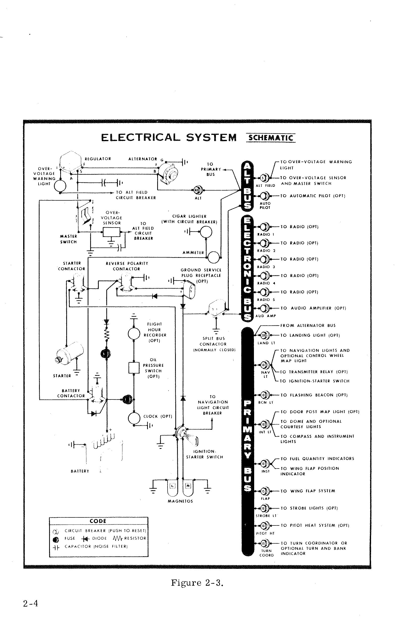
switch, when placed in the OFF position, removes the alternator from the electrical system. With this switch in the OFF position, the entire electrical load is placed on the battery. Continued operation with the alternator switch OFF will reduce battery power low enough to open the battery contactor, remove power from the alternator field, and prevent alternator restart.
Ammeter p. 19
The ammeter indicates the flow of current, in amperes, from the alternator to the battery or from the battery to the aircraft electrical system. When the engine is operating and the master switch is ON, the ammeter indicates the charging rate applied to the battery. In the event the alternator is not functioning or the electrical load exceeds the output of the alternator, the ammeter indicates the discharge rate of the battery.
Over-Voltage Sensor and Warning Light
The aircraft is equipped with an automatic over-voltage protection system consisting of an over-voltage sensor behind the instrument panel and a red warning light, labeled HIGH VOLTAGE, under the oil temperature and pressure gages.
In the event an over-voltage condition occurs, the over-voltage sensor automatically removes alternator field current and shuts down the alternator. The red warning light will then turn on, indicating to the pilot that the alternator is not operating and the aircraft battery is supplying all electrical power.
The over-voltage sensor may be reset by turning the master switch off and back on again. If the warning light does not illuminate, normal alternator charging has resumed; however, if the light does illuminate again, a malfunction has occurred, and the flight should be terminated as soon as practical.
The over-voltage warning light may be tested by momentarily turning off the ALT portion of the master switch and leaving the BAT portion turned on.
Circuit Breakers and Fuses
The majority of electrical circuits in the airplane are protected by "push-to-reset" circuit breakers mounted on the instrument panel. Ex-
ceptions to this are the optional clock, flight hour recorder, and battery contactor closing (external power) circuits which have fuses mounted adjacent to the battery. Also, the cigar lighter is protected by a manually reset type circuit breaker mounted directly on the back of the lighter behind the instrument panel.
p. 20Lighting Equipment
Exterior Lighting
Conventional navigation lights are located on the wing tips and top of the rudder. Optional lighting includes a single landing light in the cowl nose cap, a flashing beacon on the top of the vertical fin, a strobe light on each wing tip, and two courtesy lights, one under each wing, just outboard of the cabin door. The courtesy lights are controlled by the dome light switch located on the overhead console. All other exterior lights are controlled by rocker type switches located on the left switch and control panel. The switches are ON in the up position and OFF in the down position.
The two high intensity strobe lights will enhance anti-collision protection. However, the lights should be turned off when taxiing in the vicinity of other aircraft, or during flight through clouds, fog or haze.
Interior Lighting p. 21
Illumination of the instrument panel is provided by red flood lighting in the forward portion of the overhead console. The magnetic compass and radio equipment have integral lighting. A dual rheostat control on the left switch and control panel operates these lights. The inner knob, labeled PANEL, operates the instrument panel and compass lighting. The outer knob, labeled RADIO, controls all radio lighting.
A cabin dome light is located in the overhead console, and is operated by a switch adjacent to the light. To turn the light on, move the switch to the right. This will also operate the optional courtesy lights.
An optional map light may be mounted on the bottom of the pilot's control wheel. The light illuminates the lower portion of the cabin, just forward of the pilot and is helpful when checking maps and other flight data during night operations. To operate the light, first turn on the NAV LT Switch, then adjust the map light's intensity with the disk type rheostat control located on the bottom of the control wheel.
A doorpost map light is also offered as optional equipment, and is located at the top of the left forward doorpost. The light contains both red and white bulbs, and may be positioned to illuminate any area desired by the pilot. A switch on the left forward doorpost is labeled RED, OFF, and WHITE. Placing the switch in the top position will provide a red light. In the bottom position, standard white lighting is provided. The center position is OFF.
Wing Flap System
The wing flaps are electrically operated by a flap motor located in the right wing. Flap position is controlled by a switch, labeled WING FLAPS on the lower center portion of the instrument panel. Flap position is shown by an indicator on the lower right portion of the instrument panel below the right control wheel position.
To extend the wing flaps, the flap switch must be depressed and held in the DOWN position until the desired degree of extension is reached. Releasing the switch allows it to return to the center off position. Normal full flap extension in flight will require approximately 9 seconds. After the flaps reach maximum extension or retraction, limit switches will automatically shut off the flap motor.
p. 22 To retract the flaps, place the flap switch in the UP position. The switch will remain in the UP position without manual assistance due to an over-center design of the switch. Full flap retraction in flight requires approximately 7 seconds. More gradual flap retraction can be accomplished by intermittent operation of the flap switch to the UP position. After full retraction, the switch is normally returned to the center off position.
Cabin Heating, Ventilating and Defrosting System
For cabin ventilation, pull the CABIN AIR knob out. To raise the air temperature, pull the CABIN HT knob out approximately 1/4" to 1/2" for a small amount of cabin heat. Additional heat is available by pulling the knob out farther; maximum heat is available with the CABIN HT knob pulled out and the CABIN AIR knob pushed full in. When no heat is desired in the cabin, the CABIN HT knob is pushed full in.
Front cabin heat and ventilating air is supplied by outlet holes spaced across a cabin manifold just forward of the pilot's and copilot's feet. Rear cabin heat and air is supplied by two ducts from the manifold, one extending down each side of the cabin to an outlet at the front door post at floor level. Windshield defrost air is also supplied by a duct leading from the cabin manifold.
Separate adjustable ventilators supply additional air; one near each upper corner of the windshield supplies air for the pilot and copilot, and two optional ventilators in the rear cabin ceiling supply air to the rear seat passengers.
Shoulder Harnesses
Shoulder harnesses are provided as standard equipment for the pilot and front seat passenger, and as optional equipment for the rear seat passengers.
Each front seat harness is attached to a rear door post just above window line and is stowed above the cabin door. When stowed, the har-
p. 23 ness is held in place by two retaining clips, one above the door and one on the front of the forward door post. When stowing the harness, place it behind both retaining clips and secure the loose end behind the retaining clip above the door. The optional rear seat shoulder harnesses are attached just below the lower corners of the rear window. Each rear seat harness is stowed behind a retaining clip located at the bottom edge of the aft side window.
To use the front and rear seat shoulder harnesses, fasten and adjust the seat belt first. Remove the harness from the stowed position, and lengthen as required by pulling on the end of the harness and the narrow release strap. Snap the harness metal stud firmly into the retaining slot adjacent to the seat belt buckle. Then adjust to length by pulling down on the free end of the harness. A properly adjusted harness will permit the occupant to lean forward enough to sit completely erect but is tight enough to prevent excessive forward movement and contact with objects during sudden deceleration. Also, the pilot will want the freedom to reach all controls easily.
Releasing and removing the shoulder harness is accomplished by pulling upward on the narrow release strap and removing the harness stud from the slot in the seat belt buckle. In an emergency, the shoulder harness may be removed by releasing the seat belt first and pulling the harness over the head by pulling up on the release strap.
Starting Engine
During engine starting, open the throttle approximately 1/8 inch. In warm temperatures, one or two strokes of the primer should be sufficient. In cold weather, up to six strokes of the primer may be necessary. If the engine is warm, no priming will be required. In extremely cold temperatures, it may be necessary to continue priming while cranking the engine.
Weak intermittent firing followed by puffs of black smoke from the exhaust stack indicates overpriming or flooding. Excess fuel can be cleared from the combustion chambers by the following procedure: Set the mixture control full lean and the throttle full open; then crank the engine through several revolutions with the starter. Repeat the starting procedure without any additional priming.
If the engine is underprimed (most likely in cold weather with a cold
p. 24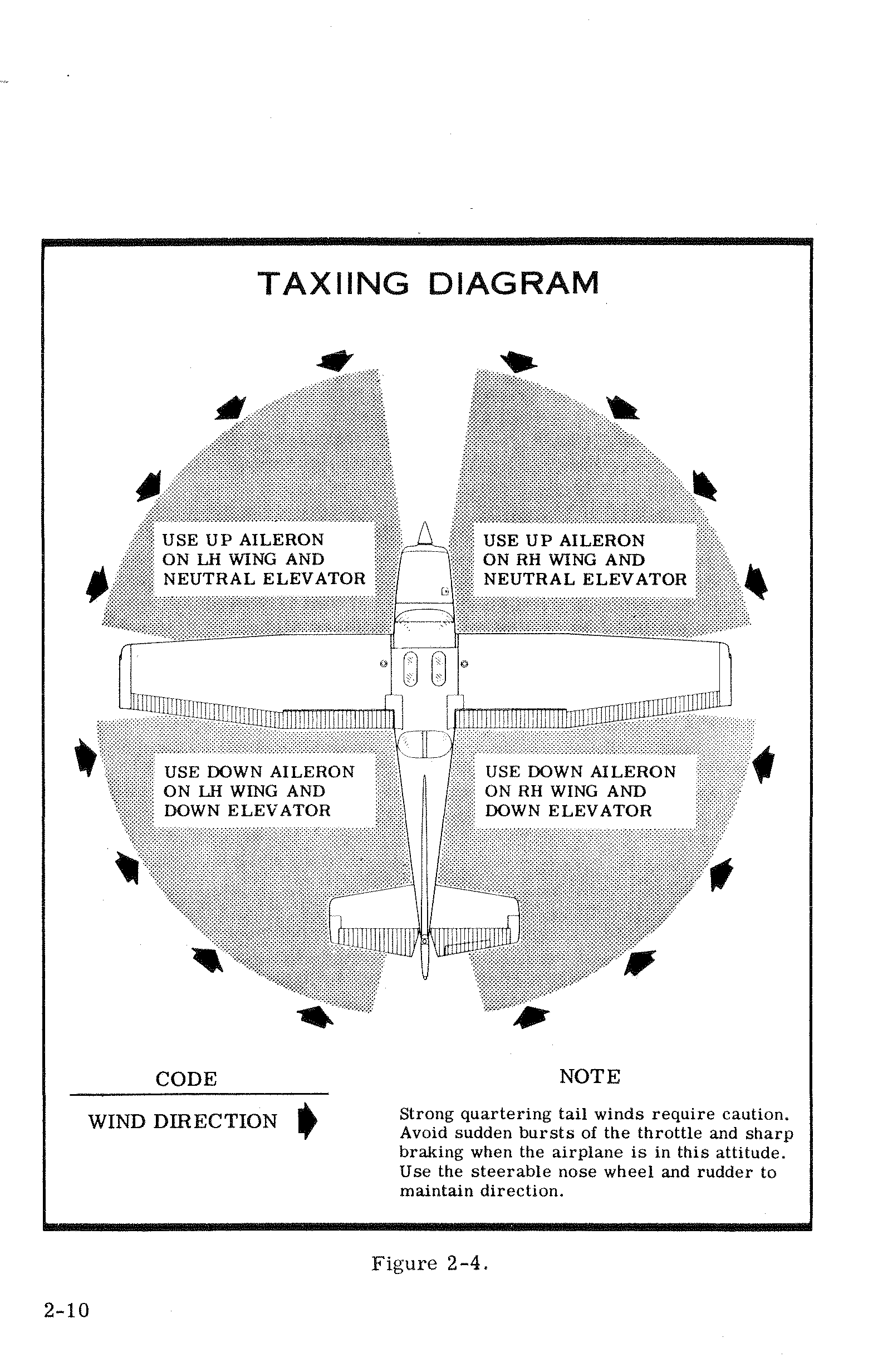
Taxiing Diagram Summary
| Wind Direction | Aileron Position | Elevator Position |
|---|---|---|
| Headwind from left | UP aileron on LH wing | Neutral |
| Headwind from right | UP aileron on RH wing | Neutral |
| Tailwind from left | DOWN aileron on LH wing | Down |
| Tailwind from right | DOWN aileron on RH wing | Down |
engine) it will not fire at all, and additional priming will be necessary. As soon as the cylinders begin to fire, open the throttle slightly to keep it running.
After starting, if the oil gage does not begin to show pressure within 30 seconds in the summertime and about twice that long in very cold weather, stop engine and investigate. Lack of oil pressure can cause serious engine damage. After starting, avoid the use of carburetor heat unless icing conditions prevail.
Taxiing p. 25
When taxiing, it is important that speed and use of brakes be held to a minimum and that all controls be utilized (see Taxiing Diagram, figure 2-4) to maintain directional control and balance.
The carburetor heat control knob should be pushed full in during all ground operations unless heat is absolutely necessary. When the knob is pulled out to the heat position, air entering the engine is not filtered.
Taxiing over loose gravel or cinders should be done at low engine speed to avoid abrasion and stone damage to the propeller tips.
Before Take-Off
Warm-Up
If the engine accelerates smoothly, the aircraft is ready for take-off. Since the engine is closely cowled for efficient in-flight engine cooling, precautions should be taken to avoid overheating during prolonged engine operation on the ground. Also, long periods of idling may cause fouled spark plugs.
Magneto Check
The magneto check should be made at 1700 RPM as follows. Move p. 26 ignition switch first to R position and note RPM. Next move switch back to BOTH to clear the other set of plugs. Then move switch to the L position, note RPM and return the switch to the BOTH position. RPM drop should not exceed 125 RPM on either magneto or show greater than 50 RPM differential between magnetos. If there is a doubt concerning operation of the ignition system, RPM checks at higher engine speeds will usually confirm whether a deficiency exists.
An absence of RPM drop may be an indication of faulty grounding of one side of the ignition system or should be cause for suspicion that the magneto timing is set in advance of the setting specified.
Alternator Check
Prior to flights where verification of proper alternator and voltage regulator operation is essential (such as night or instrument flights), a positive verification can be made by loading the electrical system momentarily (3 to 5 seconds) with the optional landing light (if so equipped), or by operating the wing flaps during the engine runup (1700 RPM). The ammeter will remain within a needle width of zero if the alternator and voltage regulator are operating properly.
Take-Off
Power Check
It is important to check full-throttle engine operation early in the take-off run. Any signs of rough engine operation or sluggish engine acceleration is good cause for discontinuing the take-off. If this occurs, you are justified in making a thorough full-throttle, static runup before another take-off is attempted. The engine should run smoothly and turn approximately 2270 to 2370 RPM with carburetor heat off and mixture full rich.
Full-throttle runups over loose gravel are especially harmful to propeller tips. When take-offs must be made over a gravel surface, it is p. 27 very important that the throttle be advanced slowly. This allows the airplane to start rolling before high RPM is developed, and the gravel will be blown back of the propeller rather than pulled into it. When unavoidable small dents appear in the propeller blades, they should be immediately corrected as described in Section V under propeller care.
Prior to take-off from fields above 3000 feet elevation, the mixture should be leaned to give maximum RPM in a full-throttle, static runup.
Wing Flap Settings
Normal and obstacle clearance take-offs are performed with wing flaps up. The use of 10° flaps will shorten the ground run approximately 10%, but this advantage is lost in the climb to a 50-foot obstacle. Therefore, the use of 10° flaps is reserved for minimum ground runs or for take-off from soft or rough fields. If 10° of flaps are used for minimum ground runs, it is preferable to leave them extended rather than retract them in the climb to the obstacle. In this case, use an obstacle clearance speed of 65 MPH. As soon as the obstacle is cleared, the flaps may be retracted as the airplane accelerates to the normal flaps-up climb speed of 80 to 90 MPH.
During a high altitude take-off in hot weather where climb would be marginal with 10° flaps, it is recommended that the flaps not be used for take-off. Flap settings greater than 10° are not recommended at any time for take-off.
Performance Charts
Consult the Take-Off Data chart in Section VI for take-off distances under various gross weight, altitude, headwind, temperature, and runway surface conditions.
Crosswind Take-Offs
Take-offs into strong crosswinds normally are performed with the minimum flap setting necessary for the field length to minimize the drift angle immediately after take-off. The airplane is accelerated to a speed slightly higher than normal, then pulled off abruptly to prevent possible settling back to the runway while drifting. When clear of the ground, make a coordinated turn into the wind to correct for drift.
Enroute Climb p. 28
Climb Data
For detailed data, refer to the Maximum Rate-Of-Climb Data chart in Section VI.
Climb Speeds
Normal climbs are performed at 80 to 90 MPH with flaps up and full throttle for best engine cooling. The mixture should be full rich below 3000 feet and may be leaned above 3000 feet for smoother engine operation. The maximum rate-of-climb speeds range from 90 MPH at sea level to 79 MPH at 10,000 feet. If an enroute obstruction dictates the use of a steep climb angle, climb at 75 MPH with flaps retracted.
Cruise
Normal cruising is done between 65% and 75% power. The power settings required to obtain these powers at various altitudes and outside air temperatures can be determined by using your Cessna Power Computer or the OPERATIONAL DATA, Section VI.
Cruising can be done more efficiently at high altitudes because of lower air density and therefore higher true airspeeds for the same power. This is illustrated in the table below, which shows performance at 75% power at various altitudes. All figures are based on lean mixture, 38 gallons of fuel (no reserve), zero wind, standard atmospheric conditions, and 2300 pounds gross weight.
To achieve the lean mixture fuel consumption figures shown in Section VI, the mixture should be leaned as follows: pull mixture control out until engine RPM peaks and begins to fall off, then enrichen slightly back to peak RPM.
Carburetor ice, as evidenced by an unexplained drop in RPM, can be removed by application of full carburetor heat. Upon regaining the origi-
p. 29Maximum Cruise Speed Performance — 75% Power
| Altitude | RPM | True Airspeed (MPH) | Range (38 Gal) |
|---|---|---|---|
| Sea Level | 2490 | 123 | 575 |
| 5000 ft. | 2600 | 128 | 600 |
| 9000 ft. | FULL THROTTLE | 132 | 620 |
nal RPM (with heat off), use the minimum amount of heat (by trial and error) to prevent ice from forming. Since the heated air causes a richer mixture, readjust the mixture setting when carburetor heat is to be used continuously in cruise flight.
The use of full carburetor heat is recommended during flight in heavy rain to avoid the possibility of engine stoppage due to excessive water ingestion or carburetor ice. The mixture setting should be readjusted for smoothest operation.
In extremely heavy rain, the use of partial carburetor heat (control approximately 2/3 out), and part throttle (closed at least one inch), may be necessary to retain adequate power. Power changes should be made cautiously followed by prompt adjustment of the mixture for smoothest operation.
Stalls
The stall characteristics are conventional and aural warning is provided by a stall warning horn which sounds between 5 and 10 MPH above the stall in all configurations.
Power-off stall speeds at maximum gross weight and aft c.g. position are presented on page 6-2 as calibrated airspeeds since indicated airspeeds are unreliable near the stall.
Spins
Intentional spins are approved in this aircraft in the utility category only. Although this aircraft is inherently resistant to spins, the follow-
p. 30ing techniques may be used to perform intentional spins for training or practice. To obtain a clean entry, decelerate the aircraft at a faster rate than is used for stalls. Then, just as the stall occurs, apply full up elevator, full rudder in the desired spin direction, and momentarily use full engine power. As the aircraft begins to spin, reduce the power to idle and maintain full pro-spin elevator and rudder deflections. The application of ailerons in the direction of the desired spin may also help obtain a clean entry.
During extended spins of two to three turns or more, the spin will tend to change into a spiral, particularly to the right. This will be accompanied by an increase in airspeed and gravity loads on the aircraft. If this occurs, recovery should be accomplished quickly by leveling the wings and recovering from the resulting dive.
To recover from an intentional or inadvertent spin, use the following procedure:
- Retard throttle to idle position.
- Apply full rudder opposite to the direction of rotation.
- After one-fourth turn, move the control wheel forward of neutral in a brisk motion.
- As the rotation stops, neutralize the rudder, and make a smooth recovery from the resulting dive.
Landings
Normal landings are made power-off with any flap setting desired. Steep slips should be avoided with flap settings greater than 20° due to a slight tendency for the elevator to oscillate under certain combinations of airspeed, sideslip angle, and center of gravity loadings.
Normal Landing
Landings should be made on the main wheels first to reduce the landing speed and subsequent need for braking in the landing roll. The nose
wheel is lowered to the runway gently after the speed has diminished to avoid unnecessary nose gear loads. This procedure is especially important in rough or soft field landings.
Short Field Landing p. 31
For short field landings, make a power-off approach at approximately 69 MPH indicated airspeed with 40° of flaps. Touchdown should be made on the main wheels first. Immediately after touchdown, lower the nose gear to the ground and apply heavy braking as required. For maximum brake effectiveness after all three wheels are on the ground, retract the flaps, hold full nose up elevator and apply maximum possible brake pressure without sliding the tires.
Crosswind Landing
When landing in a strong crosswind, use the minimum flap setting required for the field length. If flap settings greater than 20° are used in sideslips with full rudder deflection, some elevator oscillation may be felt at normal approach speeds. However, this does not affect control of the aircraft. Although the crab or combination method of drift correction may be used, the wing-low method gives the best control. After touchdown, hold a straight course with the steerable nose wheel and occasional braking if necessary.
The maximum allowable crosswind velocity is dependent upon pilot capability rather than airplane limitations. With average pilot technique, direct crosswinds of 15 knots can be handled with safety.
Balked Landing (Go-Around)
In a balked landing (go-around) climb, reduce the wing flap setting to 20° immediately after full power is applied. If the flaps were extended to 40°, the reduction to 20° may be approximated by placing the flap switch in the UP position for two seconds and then returning the switch to neutral. If obstacles must be cleared during the go-around climb, leave the wing flaps in the 10° to 20° range until the obstacles are cleared. After clearing any obstacles the flaps may be retracted as the aircraft accelerates to the normal flaps-up climb speed of 80 to 90 MPH.
Cold Weather Operation p. 32
Starting
Prior to starting on a cold morning, it is advisable to pull the propeller through several times by hand to "break loose" or "limber" the oil, thus conserving battery energy.
In extremely cold (0°F and lower) weather, the use of an external preheater and an external power source are recommended whenever possible to obtain positive starting and to reduce wear and abuse to the engine and electrical system. Pre-heat will thaw the oil trapped in the oil cooler, which probably will be congealed prior to starting in extremely cold temperatures. When using an external power source, the position of the master switch is important. Refer to Section VII under Ground Service Plug Receptacle for operating details.
Cold weather starting procedures are as follows:
With Preheat:
- Ignition Switch — OFF, Throttle — CLOSED. Prime the engine four to eight strokes as the propeller is being turned over by hand.
NOTE: Use heavy strokes of primer for best atomization of fuel. After priming, push primer all the way in and turn to locked position to avoid possibility of engine drawing fuel through the primer.
- Propeller Area — CLEAR.
- Master Switch — ON.
- Mixture — FULL RICH.
- Throttle — OPEN 1/8".
- Ignition Switch — START.
- Release ignition switch to BOTH when engine starts.
- Oil Pressure — CHECK. p. 33
Without Preheat:
- Prime the engine six to ten strokes while the propeller is being turned by hand with throttle closed. Leave primer charged and ready for stroke.
- Propeller Area — CLEAR.
- Master Switch — ON.
- Mixture — FULL RICH.
- Ignition Switch — START.
- Pump throttle rapidly to full open twice. Return to 1/8" open position.
- Release ignition switch to BOTH when engine starts.
- Continue to prime engine until it is running smoothly, or alternately pump throttle rapidly over first 1/4 to total travel.
- Oil Pressure — CHECK.
- Carburetor Heat — FULL ON after engine has started. Leave on until engine is running smoothly.
- Lock Primer.
During cold weather operations, no indication will be apparent on the oil temperature gage prior to take-off if outside air temperatures are very cold. After a suitable warm-up period (2 to 5 minutes at 1000 RPM), accelerate the engine several times to higher engine RPM. If the engine accelerates smoothly and the oil pressure remains normal and steady, the aircraft is ready for take-off.
Flight Operations p. 34
Take-off is made normally with carburetor heat off. Avoid excessive leaning in cruise.
Carburetor heat may be used to overcome any occasional engine roughness due to ice.
Refer to Section VII for cold weather equipment.
Hot Weather Operation
Refer to the general warm temperature starting information under Starting Engine in this section. Avoid prolonged engine operation on the ground.
Section III — Emergency Procedures p. 35
Emergencies caused by aircraft or engine malfunctions are extremely rare if proper pre-flight inspections and maintenance are practiced. Enroute weather emergencies can be minimized or eliminated by careful flight planning and good judgement when unexpected weather is encountered. However, should an emergency arise the basic guidelines described in this section should be considered and applied as necessary to correct the problem.
Electrical Power Supply System Malfunctions
Malfunctions in the electrical power supply system can be detected by periodic monitoring of the ammeter and over-voltage warning light; however, the cause of these malfunctions is usually difficult to determine. A broken alternator drive belt or wiring is most likely the cause of alternator failures, although other factors could cause the problem. A damaged or improperly adjusted voltage regulator can also cause malfunctions. Problems of this nature constitute an electrical emergency and should be dealt with immediately. Electrical power malfunctions usually fall into two categories: excessive rate of charge and insufficient rate of charge. The paragraphs below describe the recommended remedy for each situation.
Excessive Rate of Charge
After engine starting and heavy electrical usage at low engine speeds (such as extended taxiing) the battery condition will be low enough to accept above normal charging during the initial part of a flight. However, after thirty minutes of cruising flight, the ammeter should be indicating less than two needle widths of charging current. If the charging rate were to remain above this value on a long flight, the battery would overheat and evaporate the electrolyte at an excessive rate. Electronic components in the electrical system could be adversely affected by higher than normal voltage if a faulty voltage regulator setting is causing the p. 36 overcharging. To preclude these possibilities, an over-voltage sensor will automatically shut down the alternator and the over-voltage warning light will illuminate if the charge voltage reaches approximately 16 volts.
Assuming that the malfunction was only momentary, an attempt should be made to reactivate the alternator system. To do this, turn both sides of the master switch off and then on again. If the problem no longer exists, normal alternator charging will resume and the warning light will go off. If the light comes on again, a malfunction is confirmed. In this event, the flight should be terminated and/or the current drain on the battery minimized because the battery can supply the electrical system for only a limited period of time. If the emergency occurs at night, power must be conserved for later use of the landing light and flaps during landing.
Insufficient Rate of Charge
If the ammeter indicates a continuous discharge rate in flight, the alternator is not supplying power to the system and should be shut down since the alternator field circuit may be placing an unnecessary load on the system. All non-essential equipment should be turned OFF and the flight terminated as soon as practical.
Rough Engine Operation or Loss of Power
Carburetor Icing
A gradual loss of RPM and eventual engine roughness may result from the formation of carburetor ice. To clear the ice, apply full throttle and pull the carburetor heat knob full out until the engine runs smoothly; then remove carburetor heat and readjust the throttle. If conditions require the continued use of carburetor heat in cruise flight, use the minimum amount of heat necessary to prevent ice from forming and lean the mixture slightly for smoothest engine operation.
Spark Plug Fouling
An engine roughness in flight may be caused by one or more spark plugs becoming fouled by carbon or lead deposits. This may be verified by turning the ignition switch momentarily from BOTH to either LEFT or RIGHT position. An obvious power loss in single ignition operation is evidence of spark plug or magneto trouble. Assuming that spark plugs are the more likely cause, lean the mixture to the normal lean setting for cruising flight. If the problem does not clear up in several minutes, de-
(Continued from previous page)
termine if a richer mixture setting will produce smoother operation. If not, proceed to the nearest airport for repairs using the BOTH position of the ignition switch unless extreme roughness dictates the use of a single ignition position.Magneto Malfunction p. 37
A sudden engine roughness or misfiring is usually evidence of magneto problems. Switching from BOTH to either LEFT or RIGHT ignition switch position will identify which magneto is malfunctioning. Select different power settings and enrichen the mixture to determine if continued operation on BOTH magnetos is practicable. If not, switch to the good magneto and proceed to the nearest airport for repairs.
Low Oil Pressure
If low oil pressure is accompanied by normal oil temperature, there is a possibility the oil pressure gage or relief valve is malfunctioning. A leak in the line to the gage is not necessarily cause for an immediate precautionary landing because an orifice in this line will prevent a sudden loss of oil from the engine sump. However, a landing at the nearest airport would be advisable to inspect the source of trouble.
If a total loss of oil pressure is accompanied by a rise in oil temperature, there is reason to suspect an engine failure is imminent. Reduce engine power immediately and select a suitable forced landing field. Leave the engine running at low power during the approach, using only the minimum power required to reach the desired touchdown spot.
Forced Landings
Precautionary Landing With Engine Power
Before attempting an "off airport" landing, one should drag the landing area at a safe but low altitude to inspect the terrain for obstructions and surface conditions, proceeding as follows:
- Drag over selected field with flaps 20° and 70 MPH airspeed, noting the preferred area for touchdown for the next landing approach. Then retract flaps after well clear of all obstacles.
- On downwind leg, turn off all switches except the ignition and master switches.
- p. 38 Approach with flaps 40° at 70 MPH.
- Unlatch cabin doors prior to final approach.
- Before touchdown, turn off ignition and master switches.
- Land in a slightly tail-low attitude.
Emergency Landing Without Engine Power
If an engine stoppage occurs, establish a flaps up glide at 80 MPH. If time permits, attempt to restart the engine by checking for fuel quantity, proper fuel selector valve position, and mixture control setting. Also check that engine primer is full in and locked and ignition switch is properly positioned.
If all attempts to restart the engine fail, and a forced landing is imminent, select a suitable field and prepare for the landing as follows:
- Mixture control — IDLE CUT-OFF (pull to idle cut-off position).
- Fuel selector valve handle — OFF.
- All switches except master switch — OFF.
- Airspeed — 70 to 80 MPH (flaps up).
- Extend wing flaps as necessary within gliding distance of field.
- Airspeed — 65 to 75 MPH (flaps down).
- Master switch — OFF.
- Unlatch cabin doors prior to final approach.
- Land in a slightly tail-low attitude.
- Apply heavy braking while holding full up elevator.
Ditching
Prepare for ditching by securing or jettisoning heavy objects located in the baggage area, and collect folded coats or cushions for protection of occupant's face at touchdown. Transmit Mayday message on 121.5 MHz., giving location and intentions.
- Plan approach into wind if winds are high and seas are heavy. With heavy swells and light wind, land parallel to swells.
- Approach with flaps 40° and sufficient power for a 300 ft./min. rate of descent at 70 MPH.
- Unlatch the cabin doors.
- Maintain a continuous descent until touchdown in level attitude. Avoid a landing flare because of difficulty in judging aircraft height over a water surface.
- Place folded coat or cushion in front of face at time of touchdown.
- p. 39 Evacuate aircraft through cabin doors. If necessary, open window to flood cabin compartment for equalizing pressure so that door can be opened.
- Inflate life vests and raft (if available) after evacuation of cabin. The aircraft can not be depended on for flotation for more than a few minutes.
Disorientation in Clouds
When flying in marginal weather, the pilot should make sure that the Wing Leveler control knob (if installed) is ON. However, if the airplane is not equipped with this device or gyro horizon and directional gyro instruments, the pilot will have to rely on the turn coordinator (or turn and bank indicator) if he inadvertently flies into clouds. The following instructions assume that only one of the latter two instruments is available.
Executing a 180° Turn in Clouds
Upon entering the clouds, an immediate plan should be made to turn back as follows:
- Note the time of the minute hand and observe the position of the sweep second hand on the clock.
- When the sweep second hand indicates the nearest half-minute, initiate a standard rate left turn, holding the turn coordinator symbolic airplane wing opposite the lower left index mark for 60 seconds. Then roll back to level flight by leveling the miniature airplane.
- Check accuracy of the turn by observing the compass heading which should be the reciprocal of the original heading.
- If necessary, adjust heading primarily with skidding motions rather than rolling motions so that the compass will read more accurately.
- Maintain altitude and airspeed by cautious application of elevator control. Avoid overcontrolling by keeping the hands off the control wheel and steering only with rudder.
Emergency Let-Downs Through Clouds
If possible, obtain radio clearance for an emergency descent through clouds. To guard against a spiral dive, choose an easterly or westerly heading to minimize compass card swings due to changing bank angles. In addition, keep hands off the control wheel and steer a straight course with rudder control by monitoring the turn coordinator. Occasionally
p. 40check the compass heading and make minor corrections to hold an approximate course. Before descending into the clouds, set up a stabilized letdown condition as follows:
- Apply full rich mixture.
- Use full carburetor heat.
- Reduce power to set up a 500 to 800 ft./min. rate of descent.
- Adjust the elevator trim tab for a stabilized descent at 90 MPH.
- Keep hands off the control wheel.
- Monitor turn coordinator and make corrections by rudder alone.
- Check trend of compass card movement and make cautious corrections with rudder to stop the turn.
- Upon breaking out of clouds resume normal cruising flight.
Recovery From a Spiral Dive
If a spiral is encountered, proceed as follows:
- Close the throttle.
- Stop the turn by using coordinated aileron and rudder control to align the symbolic airplane in the turn coordinator with the horizon reference line.
- Cautiously apply elevator back pressure to slowly reduce the indicated airspeed to 90 MPH.
- Adjust the elevator trim control to maintain a 90 MPH glide.
- Keep hands off the control wheel, using rudder control to hold a straight heading.
- Apply carburetor heat.
- Clear engine occasionally, but avoid using enough power to disturb the trimmed glide.
- Upon breaking out of clouds, apply normal cruising power and resume flight.
Fires
Engine Fire During Start on Ground
Improper starting procedures such as pumping the throttle during a difficult cold weather start can cause a backfire which could ignite fuel that has accumulated in the intake duct. In this event, proceed as follows:
- Continue cranking in an attempt to get a start which would suck
Continued on next page
the flames and accumulated fuel through the carburetor and into the engine.
- If the start is successful, run the engine at 1700 RPM for a few minutes before shutting it down to inspect the damage.
- If engine start is unsuccessful, continue cranking for two or three minutes with throttle full open while ground attendants obtain fire extinguishers.
- When ready to extinguish fire, release the starter switch and turn off master switch, ignition switch, and fuel selector valve handle.
- Smother flames with fire extinguisher, seat cushion, wool blanket, or loose dirt. If practical try to remove carburetor air filter if it is ablaze.
- Make a thorough inspection of fire damage, and repair or replace damaged components before conducting another flight.
Engine Fire In Flight p. 41
Although engine fires are extremely rare in flight, the following steps should be taken if one is encountered:
- Mixture control — Pull to idle cut-off.
- Fuel selector valve handle — OFF.
- Master switch — OFF.
- Establish a 120 MPH glide.
- Cabin heat control — CLOSE.
- Select a field suitable for a forced landing.
- If fire is not extinguished, increase glide speed in an attempt to find an airspeed that will provide an incombustible mixture.
- Execute a forced landing as described in paragraph Emergency Landing Without Engine Power. Do not attempt to restart the engine.
Electrical Fire In Flight
The initial indication of an electrical fire is the odor of burning insulation. The immediate response should be to turn off the master switch. Then close off ventilating air as much as practicable to reduce the chances of a sustained fire.
If electrical power is indispensable for the flight, an attempt may be made to identify and cut off the defective circuit as follows:
- Master Switch — OFF.
- All other switches (except ignition switch) — OFF. p. 42
- Check condition of circuit breakers to identify faulty circuit if possible. Leave faulty circuit deactivated.
- Master Switch — ON.
- Select switches ON successively, permitting a short time delay to elapse after each switch is turned on until the short circuit is localized.
- Make sure fire is completely extinguished before opening ventilators.
Flight In Icing Conditions
Although flying in known icing conditions is prohibited, an unexpected icing encounter should be handled as follows:
- Turn on pitot heat switch (if installed).
- Turn back or change altitude to obtain an outside air temperature that is less conducive to icing.
- Pull cabin heat control full out to obtain windshield defroster airflow. Adjust cabin air control to get maximum defroster heat and airflow.
- Open the throttle to increase engine speed and minimize ice build up on propeller blades.
- Watch for signs of carburetor air filter ice and apply carburetor heat as required. An unexplained loss in engine speed could be caused by carburetor ice or air intake filter ice.
- Plan a landing at the nearest airport. With an extremely rapid ice build-up, select a suitable "off airport" landing site.
- With an ice accumulation of one quarter inch or more on the wing leading edges, be prepared for significantly higher stall speed.
- Leave wing flaps retracted. With a severe ice build-up on the horizontal tail, the change in wing wake airflow direction caused by wing flap extension could result in a loss of elevator effectiveness.
- Open left window and, if practical, scrape ice from a portion of the windshield for visibility in the landing approach.
- Perform a landing approach using a forward slip, if necessary, for improved visibility.
- Approach at 75 to 85 MPH, depending upon the amount of ice accumulation.
- Avoid steep turns during the landing approach.
- Perform a landing in level attitude.
Section IV — Operating Limitations p. 43
Operations Authorized
Your Cessna exceeds the requirements of airworthiness as set forth by the United States Government, and is certificated under FAA Type Certificate No. 3A12 as Cessna Model No. 172M.
The airplane may be equipped for day, night, VFR, or IFR operation. Your Cessna Dealer will be happy to assist you in selecting equipment best suited to your needs.
Maneuvers — Normal Category
This airplane is certificated in both the normal and utility category. The normal category is applicable to airplanes intended for non-aerobatic operations. These include any maneuvers incidental to normal flying, stalls (except whip stalls) and turns in which the angle of bank is not more than 60°. In connection with the foregoing, the following gross weight and flight load factors apply:
| Parameter | Value | Negative Limit |
|---|---|---|
| Gross Weight | 2300 lbs | — |
| Flight Load Factor — *Flaps Up | +3.8 | -1.52 |
| Flight Load Factor — *Flaps Down | +3.0 | — |
Maneuvers — Utility Category p. 44
This airplane is not designed for purely aerobatic flight. However, in the acquisition of various certificates such as commercial pilot, instrument pilot and flight instructor, certain maneuvers are required by the FAA. All of these maneuvers are permitted in this airplane when operated in the utility category. In connection with the utility category, the following gross weight and flight load factors apply, with maximum entry speeds for maneuvers as shown:
| Gross Weight | 2000 lbs | |
| Flight Load Factor — Flaps Up | +4.4 | −1.76 |
| Flight Load Factor — Flaps Down | +3.0 |
In the utility category, the baggage compartment and rear seat must not be occupied. No aerobatic maneuvers are approved except those listed below:
| Maneuver | Recommended Entry Speed* |
|---|---|
| Chandelles | 120 mph (104 knots) |
| Lazy Eights | 120 mph (104 knots) |
| Steep Turns | 112 mph (97 knots) |
| Spins | Slow Deceleration |
| Stalls (Except Whip Stalls) | Slow Deceleration |
*Abrupt use of the controls is prohibited above 112 MPH.
Airspeed Limitations (CAS) p. 45
The following is a list of the certificated calibrated airspeed (CAS) limitations for the aircraft.
| Speed | CAS (MPH) |
|---|---|
| Never Exceed Speed (glide or dive, smooth air) | 182 MPH |
| Maximum Structural Cruising Speed | 145 MPH |
| Maximum Speed, Flaps Extended | 100 MPH |
| *Maneuvering Speed | 112 MPH |
*The maximum speed at which you may use abrupt control travel.
Airspeed Indicator Markings
The following is a list of the certificated calibrated airspeed markings (CAS) for the aircraft.
| Marking | Range / Value | Indicator |
|---|---|---|
| Never Exceed (glide or dive, smooth air) | 182 MPH | Red line |
| Caution Range | 145–182 MPH | Yellow arc |
| Normal Operating Range | 61–145 MPH | Green arc |
| Flap Operating Range | 54–100 MPH | White arc |
Engine Operation Limitations
| Power and Speed | 150 BHP at 2700 RPM |
Engine Instrument Markings
Oil Temperature Gauge
| Normal Operating Range | Green arc |
| Maximum Allowable | 245°F (red line) |
Oil Pressure Gauge
| Minimum Idling | 25 psi (red line) |
| Normal Operating Range | 60–90 psi (green arc) |
| Maximum | 100 psi (red line) |
Fuel Quantity Indicators p. 46
| Empty (2.0 gallons unusable each tank) | E (red line) |
Tachometer
| Condition | RPM Range | Indicator |
|---|---|---|
| Normal Operating Range — At sea level | 2200–2500 RPM | Inner green arc |
| Normal Operating Range — At 5,000 feet | 2200–2600 RPM | Middle green arc |
| Normal Operating Range — At 10,000 feet | 2200–2700 RPM | Outer green arc |
| Maximum Allowable | 2700 RPM | Red line |
Carburetor Air Temperature Gauge (Optional)
| Icing Range | −15° to 5°C (yellow arc) |
Weight and Balance
The following information will enable you to operate your Cessna within the prescribed weight and center of gravity limitations. To figure the weight and balance for your particular airplane, use the Sample Problem, Loading Graph, and Center of Gravity Moment Envelope as follows:
Take the licensed empty weight and moment from the Weight and Balance and Installed Equipment Data sheet (or changes noted on FAA Form 337) carried in your airplane, and write them down in the column titled YOUR AIRPLANE on the Sample Loading Problem.
Use the Loading Graph to determine the moment/1000 for each additional item to be carried, then list these on the loading problem.
Total the weights and moments/1000 and plot these values on the Center of Gravity Moment Envelope to determine whether the point falls within the envelope, and if the loading is acceptable.
Loading Arrangements p. 47
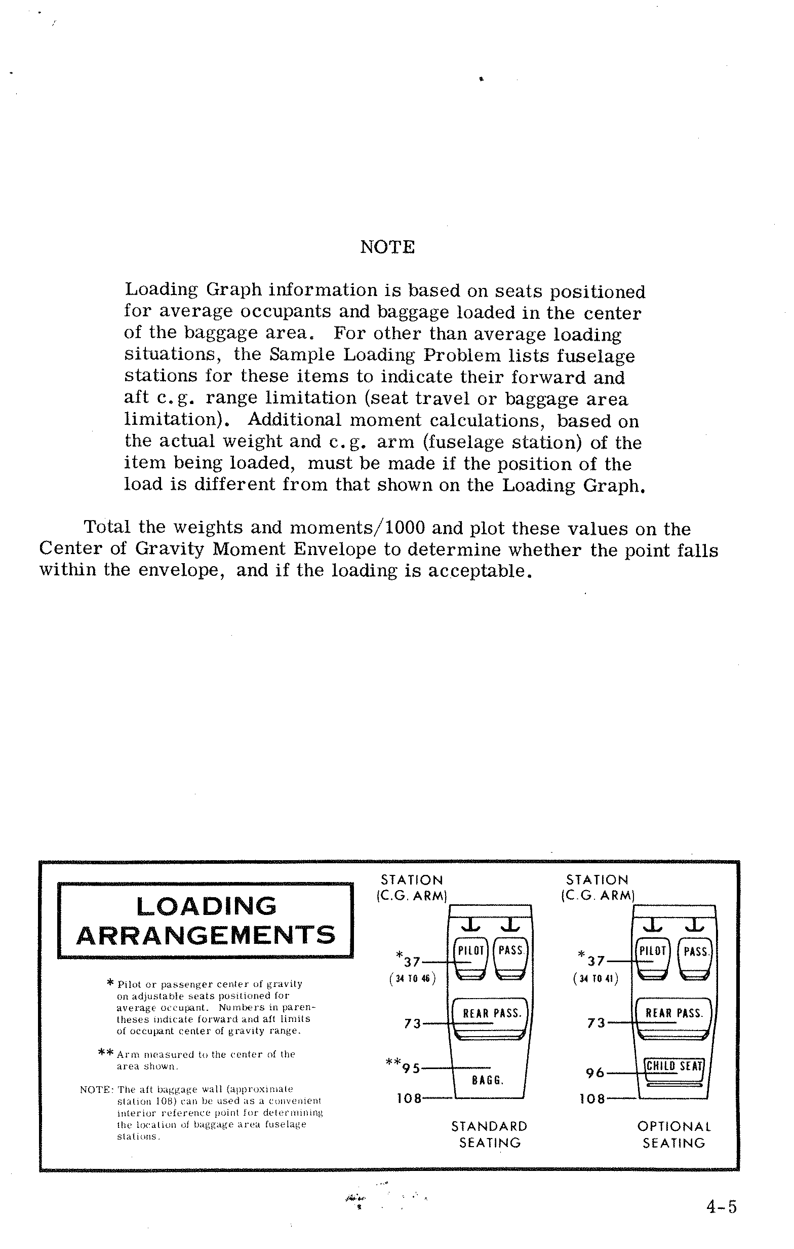
| Location | Station (C.G. Arm) | Standard Seating | Optional Seating |
|---|---|---|---|
| Pilot / Front Passenger* | *37 (range: 34 to 46) | ✓ | ✓ (34 to 41) |
| Rear Passengers | 73 | ✓ | ✓ |
| Baggage** | **95 | ✓ (Bagg.) | — |
| Child Seat | 96 | — | ✓ |
| Aft limit | 108 | ✓ | ✓ |
- * Pilot or passenger center of gravity on adjustable seats positioned for average occupant. Numbers in parentheses indicate forward and aft limits of occupant center of gravity range.
- ** Arm measured to the center of the area shown.
- NOTE: The aft baggage wall (approximate station 108) can be used as a convenient interior reference point for determining the location of baggage area fuselage stations.
Sample Loading Problem p. 48
| # | Item | Sample Airplane | Your Airplane | ||
|---|---|---|---|---|---|
| Weight (lbs.) | Moment (lb.-ins./1000) | Weight (lbs.) | Moment (lb.-ins./1000) | ||
| 1. | Licensed Empty Weight (Sample Airplane) | 1364 | 51.7 | ||
| 2. | Oil (8 qts. — The weight of full oil may be used for all calculations) | 15 | -0.2 | 15 | -0.2 |
| 3. | Fuel (Standard — 38 Gal at 6#/Gal) | 228 | 10.9 | ||
| Fuel (Long Range — 48 Gal at 6#/Gal) | |||||
| 4. | Pilot and Front Passenger (Station 34 to 46) | 340 | 12.6 | ||
| 5. | Rear Passengers | 340 | 24.8 | ||
| 6. | Baggage (or Passenger on Child's Seat) (Station 82 to 108) | 13 | 1.2 | ||
| 7. | TOTAL WEIGHT AND MOMENT | 2300 | 101.0 | ||
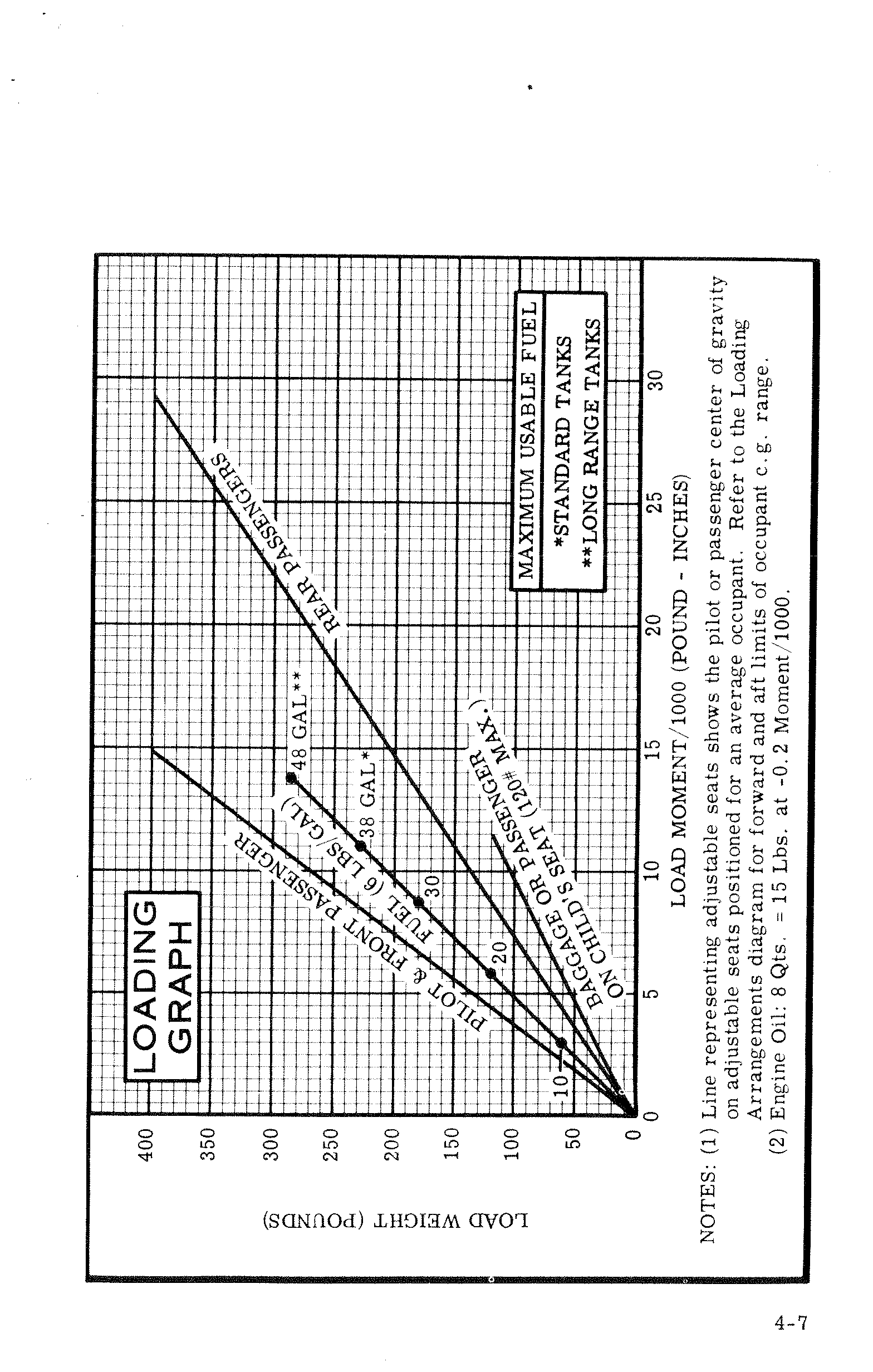
| Load Item | Example Weight (lbs) | Approx. Moment/1000 (lb-in) | Notes |
|---|---|---|---|
| Pilot & Front Passenger | ~100–400 | ~3–13 | Adjustable seats; line shows average occupant c.g. — refer to Loading Arrangements diagram for forward/aft limits |
| Fuel (6 lbs/gal) — 10 gal | 60 | ~2 | — |
| Fuel (6 lbs/gal) — 20 gal | 120 | ~4 | — |
| Fuel (6 lbs/gal) — 30 gal | 180 | ~6 | — |
| Fuel (6 lbs/gal) — 38 gal * | 228 | ~10 | *Maximum usable — Standard Tanks |
| Fuel (6 lbs/gal) — 48 gal ** | 288 | ~13 | **Maximum usable — Long Range Tanks |
| Rear Passengers | ~100–400 | ~17–30 | — |
| Baggage or Passenger on Child's Seat | 120 max | ~5–12 | 120 lb maximum |
| Engine Oil — 8 qts | 15 | −0.2 | 8 Qts = 15 lbs at −0.2 Moment/1000 |
Engine Oil: 8 Qts. = 15 Lbs. at −0.2 Moment/1000.
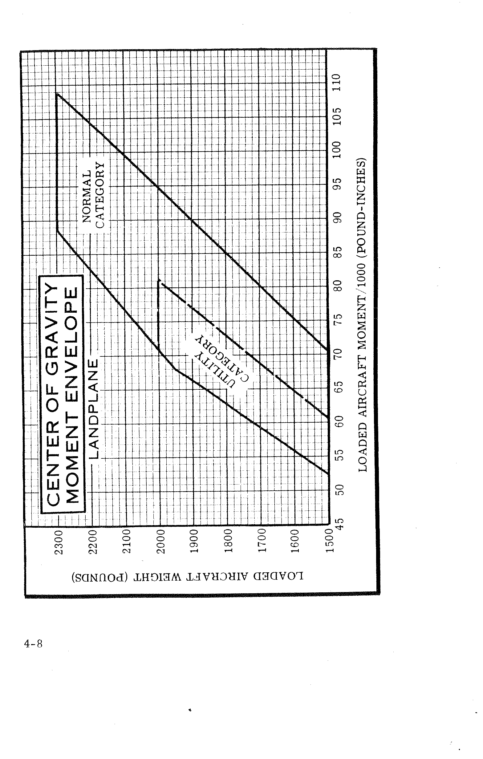
| Category | Weight (lbs) | Forward Moment/1000 Limit (lb-in) | Aft Moment/1000 Limit (lb-in) |
|---|---|---|---|
| Utility Category | 1500 | ~52.5 | ~64 |
| Utility Category | 1800 | ~58.5 | ~70 |
| Utility Category | 2000 (max) | ~63 | ~70 |
| Normal Category | 1500 | ~68 | ~82 |
| Normal Category | 1800 | ~74 | ~90 |
| Normal Category | 2000 | ~78.5 | ~95 |
| Normal Category | 2300 (max) | ~85 | ~109 |
Section V — Care of the Airplane p. 51
If your airplane is to retain that new plane performance and dependability, certain inspection and maintenance requirements must be followed. It is wise to follow a planned schedule of lubrication and preventive maintenance based on climatic and flying conditions encountered in your locality.
Keep in touch with your Cessna Dealer and take advantage of his knowledge and experience. He knows your airplane and how to maintain it. He will remind you when lubrications and oil changes are necessary, and about other seasonal and periodic services.
Ground Handling
The airplane is most easily and safely maneuvered by hand with the tow-bar attached to the nose wheel. When towing with a vehicle, do not exceed the nose gear turning angle of 30° either side of center, or damage to the gear will result. If the airplane is towed or pushed over a rough surface during hangaring, watch that the normal cushioning action of the nose strut does not cause excessive vertical movement of the tail and the resulting contact with low hangar doors or structure. A flat nose wheel tire or deflated strut will also increase tail height.
Mooring Your Airplane
Proper tie-down procedure is your best precaution against damage to your parked airplane by gusty or strong winds. To tie down your airplane securely, proceed as follows:
- Set the parking brake and install the control wheel lock.
- Tie sufficiently strong ropes or chains (700 pounds tensile strength) to wing, tail and nose tie-down rings and secure each rope to a ramp tie-down.
- Install a surface control lock over the fin and rudder.
- Install a pitot tube cover.
Windshield & Windows p. 52
The plastic windshield and windows should be cleaned with an aircraft windshield cleaner. Apply the cleaner sparingly with soft cloths, and rub with moderate pressure until all dirt, oil scum and bug stains are removed. Allow the cleaner to dry, then wipe it off with soft flannel cloths.
If a windshield cleaner is not available, the plastic can be cleaned with soft cloths moistened with Stoddard solvent to remove oil and grease.
Follow by carefully washing with a mild detergent and plenty of water. Rinse thoroughly, then dry with a clean moist chamois. Do not rub the plastic with a dry cloth since this builds up an electrostatic charge which attracts dust. Waxing with a good commercial wax will finish the cleaning job. A thin, even coat of wax, polished out by hand with clean soft flannel cloths, will fill in minor scratches and help prevent further scratching.
Do not use a canvas cover on the windshield unless freezing rain or sleet is anticipated since the cover may scratch the plastic surface.
Painted Surfaces
The painted exterior surfaces of your new Cessna have a durable, long lasting finish and, under normal conditions, require no polishing or buffing. Approximately 15 days are required for the paint to cure completely; in most cases, the curing period will have been completed prior to delivery of the airplane. In the event that polishing or buffing is required within the curing period, it is recommended that the work be done by someone experienced in handling uncured paint. Any Cessna Dealer can accomplish this work.
p. 53 Generally, the painted surfaces can be kept bright by washing with water and mild soap, followed by a rinse with water and drying with cloths or a chamois. Harsh or abrasive soaps or detergents which cause corrosion or scratches should never be used. Remove stubborn oil and grease with a cloth moistened with Stoddard solvent.
Waxing is unnecessary to keep the painted surfaces bright. However, if desired, the airplane may be waxed with a good automotive wax. A heavier coating of wax on the leading edges of the wings and tail and on the engine nose cap and propeller spinner will help reduce the abrasion encountered in these areas.
When the airplane is parked outside in cold climates and it is necessary to remove ice before flight, care should be taken to protect the painted surfaces during ice removal with chemical liquids. A 50-50 solution of isopropyl alcohol and water will satisfactorily remove ice accumulations without damaging the paint. A solution with more than 50% alcohol is harmful and should be avoided. While applying the de-icing solution, keep it away from the windshield and cabin windows since the alcohol will attack the plastic and may cause it to craze.
Aluminum Surfaces
The clad aluminum surfaces of your Cessna may be washed with clear water to remove dirt; oil and grease may be removed with gasoline, naphtha, carbon tetrachloride or other non-alkaline solvents. Dulled aluminum surfaces may be cleaned effectively with an aircraft aluminum polish.
After cleaning, and periodically thereafter, waxing with a good automotive wax will preserve the bright appearance and retard corrosion. Regular waxing is especially recommended for airplanes operated in salt water areas as a protection against corrosion.
Propeller Care
Preflight inspection of propeller blades for nicks, and wiping them occasionally with an oily cloth to clean off grass and bug stains will assure long, trouble-free service. Small nicks on the propeller, particularly near the tips and on the leading edges, should be dressed out as soon as possible since these nicks produce stress concentrations, and if p. 54 ignored, may result in cracks. Never use an alkaline cleaner on the blades; remove grease and dirt with carbon tetrachloride or Stoddard solvent.
Interior Care
To remove dust and loose dirt from the upholstery and carpet, clean the interior regularly with a vacuum cleaner.
Blot up any spilled liquid promptly, with cleansing tissue or rags. Don't pat the spot; press the blotting material firmly and hold it for several seconds. Continue blotting until no more liquid is taken up. Scrape off sticky materials with a dull knife, then spot-clean the area.
Oily spots may be cleaned with household spot removers, used sparingly. Before using any solvent, read the instructions on the container and test it on an obscure place on the fabric to be cleaned. Never saturate the fabric with a volatile solvent; it may damage the padding and backing materials.
Soiled upholstery and carpet may be cleaned with foam-type detergent, used according to the manufacturer's instructions. To minimize wetting the fabric, keep the foam as dry as possible and remove it with a vacuum cleaner.
If your airplane is equipped with leather seating, cleaning of the seats is accomplished using a soft cloth or sponge dipped in mild soap suds. The soap suds, used sparingly, will remove traces of dirt and grease. The soap should be removed with a clean damp cloth.
The plastic trim, headliner, instrument panel and control knobs need only be wiped off with a damp cloth. Oil and grease on the control wheel and control knobs can be removed with a cloth moistened with Stoddard solvent. Volatile solvents, such as mentioned in paragraphs on care of the windshield, must never be used since they soften and craze the plastic.
Flyable Storage
Aircraft placed in non-operational storage for a maximum of 30 days or those which receive only intermittent operational use for the first 25
hours are considered in flyable storage status. Every seventh day during these periods, the propeller should be rotated by hand through five revolutions. This action "limbers" the oil and prevents any accumulation of corrosion on engine cylinder walls.
After 30 days, the aircraft should be flown for 30 minutes or a ground runup should be made just long enough to produce an oil temperature within the lower green arc range. Excessive ground runup should be avoided.
Engine runup also helps to eliminate excessive accumulations of water in the fuel system and other air spaces in the engine. Keep fuel tanks full to minimize condensation in the tanks. Keep the battery fully charged to prevent the electrolyte from freezing in cold weather. If the aircraft is to be stored temporarily, or indefinitely, refer to the Service Manual for proper storage procedures.
Inspection Service and Inspection Periods
With your airplane you will receive a Customer Care Program book. Coupons attached to the Program book entitle you to an initial inspection and the first 100-hour inspection at no charge. If you take delivery from your Dealer, he will perform the initial inspection before delivery of the airplane to you. If you pick up the airplane at the factory, plan to take it to your Dealer reasonably soon after you take delivery on it. This will permit him to check it over and to make any minor adjustments that may appear necessary. Also, plan an inspection by your Dealer at 100 hours or 180 days, whichever comes first. This inspection also is performed by your Dealer for you at no charge. While these important inspections will be performed for you by any Cessna Dealer, in most cases you will prefer to have the Dealer from whom you purchased the airplane accomplish this work.
p. 56
Federal Aviation Regulations require that all airplanes have a periodic (annual) inspection as prescribed by the administrator, and performed by a person designated by the administrator. In addition, 100-hour periodic inspections made by an "appropriately-rated mechanic" are required if the airplane is flown for hire. The Cessna Aircraft Company recommends the 100-hour periodic inspection for your airplane. The procedure for this 100-hour inspection has been carefully worked out by the factory and is followed by the Cessna Dealer Organization. The complete familiarity of the Cessna Dealer Organization with Cessna equipment and with factory-approved procedures provides the highest type of service possible at lower cost.
Aircraft File
There are miscellaneous data, information and licenses that are a part of the aircraft file. The following is a check list for that file. In addition, a periodic check should be made of the latest Federal Aviation Regulations to ensure that all data requirements are met.
A. To be displayed in the aircraft at all times:
- Aircraft Airworthiness Certificate (FAA Form 8100-2).
- Aircraft Registration Certificate (FAA Form 8050-3).
- Aircraft Radio Station License, if transmitter installed (FCC Form 556).
B. To be carried in the aircraft at all times:
- Weight and Balance, and associated papers (latest copy of the Repair and Alteration Form, FAA Form 337, if applicable).
- Aircraft Equipment List.
C. To be made available upon request:
- Aircraft Log Book.
- Engine Log Book.
- Owner Follow-Up System
Most of the items listed are required by the United States Federal Aviation Regulations. Since the regulations of other nations may require other documents and data, owners of exported aircraft should check with their own aviation officials to determine their individual requirements.
MAA Plate/Finish and Trim Plate p. 57
Information concerning the Type Certificate Number (TC), Production Certificate Number (PC), Model Number and Serial Number of your particular aircraft can be found on the MAA (Manufacturers Aircraft Association) plate located on the lower part of the left forward door post.
A Finish and Trim plate contains a code describing the interior color scheme and exterior paint combination of the aircraft. The code may be used in conjunction with an applicable Parts Catalog if finish and trim information is needed. This plate is located just above the MAA plate on the left forward door post.
Lubrication and Servicing Procedures p. 58
Specific servicing information is provided here for items requiring daily attention. A Servicing Intervals Check List is included to inform the pilot when to have other items checked and serviced.
Daily
- FUEL TANK FILLERS
- Service after each flight with 80/87 minimum grade fuel. The capacity of each tank is 21 gallons. When optional long range tanks are installed, the capacity of each tank is 26 gallons. (To ensure maximum fuel capacity when refueling, place the fuel selector valve in either LEFT or RIGHT position to prevent cross-feeding.)
- FUEL STRAINER
- Before the first flight of the day and after each refueling, pull out fuel strainer drain knob for about four seconds, to clear fuel strainer of possible water and sediment. Release drain knob, then check that strainer drain is closed after draining. If water is observed, there is a possibility that the fuel tank sumps contain water. Thus, the fuel tank sump drain plugs and fuel selector valve drain plug should be removed to check for the presence of water.
- OIL DIPSTICK
- Check oil level before each flight. Do not operate on less than 6 quarts. To minimize loss of oil through breather, fill to 7 quart level for normal flights of less than 3 hours. For extended flight, fill to 8 quarts. If optional oil filter is installed, one additional quart is required when the filter element is changed.
- OIL FILLER
-
When preflight check shows low oil level, service with aviation grade engine oil:
- SAE 50 above 60°F
- SAE 10W30 or SAE 30 at temperatures from 0° to 70°F
- SAE 10W30 or SAE 20 at temperatures below 10°F
(Multi-viscosity oil with a range of SAE 10W30 is recommended for improved starting and lubrication during warm-up in cold weather.) Detergent or dispersant oil, conforming to Specification No. MIL-L-22851, must be used. Your Cessna Dealer can supply approved grades of oil.
Servicing Intervals Check List p. 59
First 25 Hours
- ENGINE OIL SUMP, OIL COOLER AND OIL FILTER — After first 25 hours of operation, drain engine oil sump and oil cooler and clean both the oil suction strainer and oil pressure screen. If an optional oil filter is installed, change filter element at this time. Refill sump with straight mineral oil (non-detergent) and use until a total of 50 hours have accumulated or oil consumption has stabilized, then change to detergent oil.
Each 50 Hours
- BATTERY — Check and service. Check oftener (at least every 30 days) if operating in hot weather.
- ENGINE OIL SUMP, OIL COOLER AND OIL FILTER — On aircraft not equipped with an optional oil filter, drain the engine oil sump and oil cooler and clean both the oil suction strainer and oil pressure screen. On the aircraft which have an optional oil filter, the oil change interval may be extended to 100-hour intervals providing the oil filter element is changed at 50-hour intervals. Change engine oil at least every four months even though less than the recommended hours have accumulated. Reduce intervals for prolonged operation in dusty areas, cold climates, or when short flights and long idle periods result in sludging conditions.
- CARBURETOR AIR FILTER — Clean or replace. Under extremely dusty conditions, daily maintenance of the filter is recommended.
- NOSE GEAR TORQUE LINKS — Lubricate. When operating under dusty conditions, more frequent lubrication is recommended.
Each 100 Hours
- SPARK PLUGS — Clean, test and regap.
- BRAKE MASTER CYLINDERS — Check and fill.
- SHIMMY DAMPENER — Check and fill.
- FUEL STRAINER — Disassemble and clean.
- FUEL TANK SUMP DRAINS — Drain water and sediment.
- FUEL SELECTOR VALVE DRAIN PLUG — Drain water and sediment.
- SUCTION RELIEF VALVE INLET SCREEN (OPT) — Clean.
Servicing Intervals Check List (Continued) p. 60
Each 500 Hours
- VACUUM SYSTEM AIR FILTER (OPT) — Replace filter element. Replace sooner if suction gage reading drops to 4.6 in. Hg.
- WHEEL BEARINGS — Lubricate at first 100 hours and at 500 hours thereafter. Reduce lubrication interval to 100 hours when operating in dusty or seacoast areas, during periods of extensive taxiing, or when numerous take-offs and landings are made.
As Required
- NOSE GEAR SHOCK STRUT — Fill with hydraulic fluid and inflate with air to 45 psi.
Servicing Intervals of items in the preceding check list are recommended by The Cessna Aircraft Company. Government regulations may require that additional items be inspected, serviced or tested at specific intervals for various types of flight operations. For these regulations, owners should check with aviation officials in the country where the aircraft is being operated.
Owner Follow-Up System p. 61
Your Cessna Dealer has an owner follow-up system to notify you when he receives information that applies to your Cessna. In addition, if you wish, you may choose to receive similar notification, in the form of Service Letters, directly from the Cessna Customer Services Department. A subscription form is supplied in your Customer Care Program book for your use, should you choose to request this service. Your Cessna Dealer will be glad to supply you with details concerning these follow-up programs, and stands ready through his Service Department to supply you with fast, efficient, low cost service.
Publications
Various publications and flight operation aids are furnished in the aircraft when delivered from the factory. These items are listed below.
- OWNER'S MANUALS FOR YOUR AIRCRAFT, ELECTRONICS AND AUTOPILOT
- POWER COMPUTER
- SALES AND SERVICE DEALER DIRECTORY
The following additional publications, plus many other supplies that are applicable to your aircraft, are available from your Cessna Dealer.
- SERVICE MANUALS AND PARTS CATALOGS FOR YOUR AIRCRAFT, ENGINE AND ACCESSORIES, ELECTRONICS AND AUTOPILOT
Your Cessna Dealer has a current catalog of all available Customer Services Supplies, many of which he keeps on hand. If supplies are not in stock, your Cessna Dealer will be happy to order for you.
Section VI — Operational Data p. 63
The operational data shown on the following pages are compiled from actual tests with the aircraft and engine in good condition and using average piloting technique and best power mixture. You will find this data a valuable aid when planning your flights.
A power setting selected from the range chart usually will be more efficient than a random setting, since it will permit you to estimate your fuel consumption more accurately. You will find that using the charts and your Power Computer will pay dividends in overall efficiency.
Cruise and range performance shown in this section is based on the use of a McCauley 1C160/CTM 7553 propeller and a standard equipped Skyhawk. Other conditions for the performance data are shown in the chart headings. Allowances for fuel reserve, headwinds, take-off and climb, and variations in mixture leaning technique should be made and are in addition to those shown on the chart. Other indeterminate variables such as carburetor metering characteristics, engine and propeller conditions, externally-mounted optional equipment and turbulence of the atmosphere may account for variations of 10% or more in maximum range.
Remember that the charts contained herein are based on standard day conditions. For more precise power, fuel consumption, and endurance information, consult the Cessna Power Computer supplied with your aircraft. With the Power Computer, you can easily take into account temperature variations from standard at any flight altitude.
Airspeed Correction Table p. 64
| Speed Type | 40 | 50 | 60 | 70 | 80 | 90 | 100 | 110 | 120 | 130 | 140 | |
|---|---|---|---|---|---|---|---|---|---|---|---|---|
| IAS (MPH) | → | 40 | 50 | 60 | 70 | 80 | 90 | 100 | 110 | 120 | 130 | 140 |
| Flaps Up | CAS | 53 | 58 | 64 | 72 | 80 | 89 | 99 | 109 | 120 | 130 | 141 |
| Flaps Down | CAS | 49 | 55 | 63 | 72 | 82 | 92 | 101 | ● | ● | ● | ● |
Stall Speeds — MPH CAS
| Gross Weight | Condition | 0° Bank | 20° Bank | 40° Bank | 60° Bank |
|---|---|---|---|---|---|
| 2300 lbs. | Flaps Up | 57 | 59 | 65 | 81 |
| Flaps 10° | 52 | 54 | 59 | 74 | |
| Flaps 40° | 49 | 51 | 56 | 69 | |
| Power Off — Aft CG | |||||
Take-Off Data p. 65
Take-Off Distance from Hard Surface Runway — Flaps Up
| Gross Weight (lbs) | IAS at 50 ft (MPH) | Headwind (Knots) | At Sea Level & 59°F | At 2500 Ft. & 50°F | At 5000 Ft. & 41°F | At 7500 Ft. & 32°F | ||||
|---|---|---|---|---|---|---|---|---|---|---|
| Ground Run (ft) | Total to Clear 50 ft Obs (ft) | Ground Run (ft) | Total to Clear 50 ft Obs (ft) | Ground Run (ft) | Total to Clear 50 ft Obs (ft) | Ground Run (ft) | Total to Clear 50 ft Obs (ft) | |||
| 2300 | 68 | 0 | 865 | 1525 | 1040 | 1910 | 1255 | 2480 | 1565 | 3855 |
| 10 | 615 | 1170 | 750 | 1485 | 920 | 1955 | 1160 | 3110 | ||
| 20 | 405 | 850 | 505 | 1100 | 630 | 1480 | 810 | 2425 | ||
| 2000 | 63 | 0 | 630 | 1095 | 755 | 1325 | 905 | 1625 | 1120 | 2155 |
| 10 | 435 | 820 | 530 | 1005 | 645 | 1250 | 810 | 1685 | ||
| 20 | 275 | 580 | 340 | 720 | 425 | 910 | 595 | 1255 | ||
| 1700 | 58 | 0 | 435 | 780 | 520 | 920 | 625 | 1095 | 765 | 1370 |
| 10 | 290 | 570 | 355 | 680 | 430 | 820 | 535 | 1040 | ||
| 20 | 175 | 385 | 215 | 470 | 270 | 575 | 345 | 745 | ||
- Increase distance 10% for each 25°F above standard temperature for particular altitude.
- For operation on a dry, grass runway, increase distances (both "ground run" and "total to clear 50 ft. obstacle") by 7% of the "total to clear 50 ft. obstacle" figure.
Maximum Rate-of-Climb Data
| Gross Weight (lbs) | At Sea Level & 59°F | At 5000 Ft. & 41°F | At 10,000 Ft. & 23°F | At 15,000 Ft. & 5°F | |||||||||||
|---|---|---|---|---|---|---|---|---|---|---|---|---|---|---|---|
| IAS (MPH) | Rate of Climb (ft/min) | Gal. of Fuel Used | IAS (MPH) | Rate of Climb (ft/min) | From S.L. Fuel Used | IAS (MPH) | Rate of Climb (ft/min) | From S.L. Fuel Used | IAS (MPH) | Rate of Climb (ft/min) | From S.L. Fuel Used | ||||
| 2300 | 90 | 645 | 1.0 | 85 | 435 | 2.6 | 79 | 230 | 4.8 | 73 | 20 | 11.5 | |||
| 2000 | 86 | 840 | 1.0 | 80 | 610 | 2.2 | 74 | 380 | 3.6 | 68 | 155 | 6.3 | |||
| 1700 | 82 | 1085 | 1.0 | 76 | 825 | 1.9 | 70 | 570 | 2.9 | 64 | 315 | 4.4 | |||
- Flaps up, full throttle, mixture leaned for smooth operation above 3000 ft.
- Fuel used includes warm up and take-off allowance.
- For hot weather, decrease rate of climb 20 ft./min. for each 10°F above standard day temperature for particular altitude.
Cruise & Range Performance — Skyhawk p. 66
Gross Weight: 2300 Lbs. | Conditions: Standard | Wind: Zero | Mixture: Lean
| ALT. (ft) |
RPM | % BHP | TAS (MPH) |
GAL / HOUR |
38 GAL (NO RESERVE) | 48 GAL (NO RESERVE) | ||
|---|---|---|---|---|---|---|---|---|
| ENDR. HOURS | RANGE MILES | ENDR. HOURS | RANGE MILES | |||||
| 2500 | 2700 | 86 | 134 | 9.7 | 3.9 | 525 | 4.9 | 660 |
| 2600 | 79 | 129 | 8.6 | 4.4 | 570 | 5.6 | 720 | |
| 2500 | 72 | 123 | 7.8 | 4.9 | 600 | 6.2 | 760 | |
| 2400 | 65 | 117 | 7.2 | 5.3 | 620 | 6.7 | 780 | |
| 2300 | 58 | 111 | 6.7 | 5.7 | 630 | 7.2 | 795 | |
| 2200 | 52 | 103 | 6.3 | 6.1 | 625 | 7.7 | 790 | |
| 5000 | 2700 | 82 | 134 | 9.0 | 4.2 | 565 | 5.3 | 710 |
| 2600 | 75 | 128 | 8.1 | 4.7 | 600 | 5.9 | 760 | |
| 2500 | 68 | 122 | 7.4 | 5.1 | 625 | 6.4 | 790 | |
| 2400 | 61 | 116 | 6.9 | 5.5 | 635 | 6.9 | 805 | |
| 2300 | 55 | 108 | 6.5 | 5.9 | 635 | 7.4 | 805 | |
| 2200 | 49 | 100 | 6.0 | 6.3 | 630 | 7.9 | 795 | |
| 7500 | 2700 | 78 | 133 | 8.4 | 4.5 | 600 | 5.7 | 755 |
| 2600 | 71 | 127 | 7.7 | 4.9 | 625 | 6.2 | 790 | |
| 2500 | 64 | 121 | 7.1 | 5.3 | 645 | 6.7 | 810 | |
| 2400 | 58 | 113 | 6.7 | 5.7 | 645 | 7.2 | 820 | |
| 2300 | 52 | 105 | 6.2 | 6.1 | 640 | 7.7 | 810 | |
| 10,000 | 2650 | 70 | 129 | 7.6 | 5.0 | 640 | 6.3 | 810 |
| 2600 | 67 | 125 | 7.3 | 5.2 | 650 | 6.5 | 820 | |
| 2500 | 61 | 118 | 6.9 | 5.5 | 655 | 7.0 | 830 | |
| 2400 | 55 | 110 | 6.4 | 5.9 | 650 | 7.5 | 825 | |
| 2300 | 49 | 100 | 6.0 | 6.3 | 635 | 8.0 | 800 | |
| 12,500 | 2600 | 63 | 123 | 7.0 | 5.4 | 665 | 6.8 | 840 |
| 2500 | 57 | 115 | 6.6 | 5.8 | 665 | 7.3 | 835 | |
| 2400 | 51 | 105 | 6.2 | 6.1 | 645 | 7.8 | 815 | |
Figure 6-4.
Landing Data p. 67
Landing Distance on Hard Surface Runway — No Wind · 40° Flaps · Power Off
| GROSS WEIGHT (LBS.) |
APPROACH IAS (MPH) |
@ S.L. & 59°F | @ 2500 ft. & 50°F | @ 5000 ft. & 41°F | @ 7500 ft. & 32°F | ||||
|---|---|---|---|---|---|---|---|---|---|
| GROUND ROLL | TOTAL TO CLEAR 50' OBS. | GROUND ROLL | TOTAL TO CLEAR 50' OBS. | GROUND ROLL | TOTAL TO CLEAR 50' OBS. | GROUND ROLL | TOTAL TO CLEAR 50' OBS. | ||
| 2300 | 69 | 520 | 1250 | 560 | 1310 | 605 | 1385 | 650 | 1455 |
- Reduce landing distance 10% for each 5 knot headwind.
- For operation on a dry, grass runway, increase distances (both "ground roll" and "total to clear 50 ft. obstacle") by 20% of the "total to clear 50 ft. obstacle" figure.
Figure 6-5.
Maximum Glide p. 68
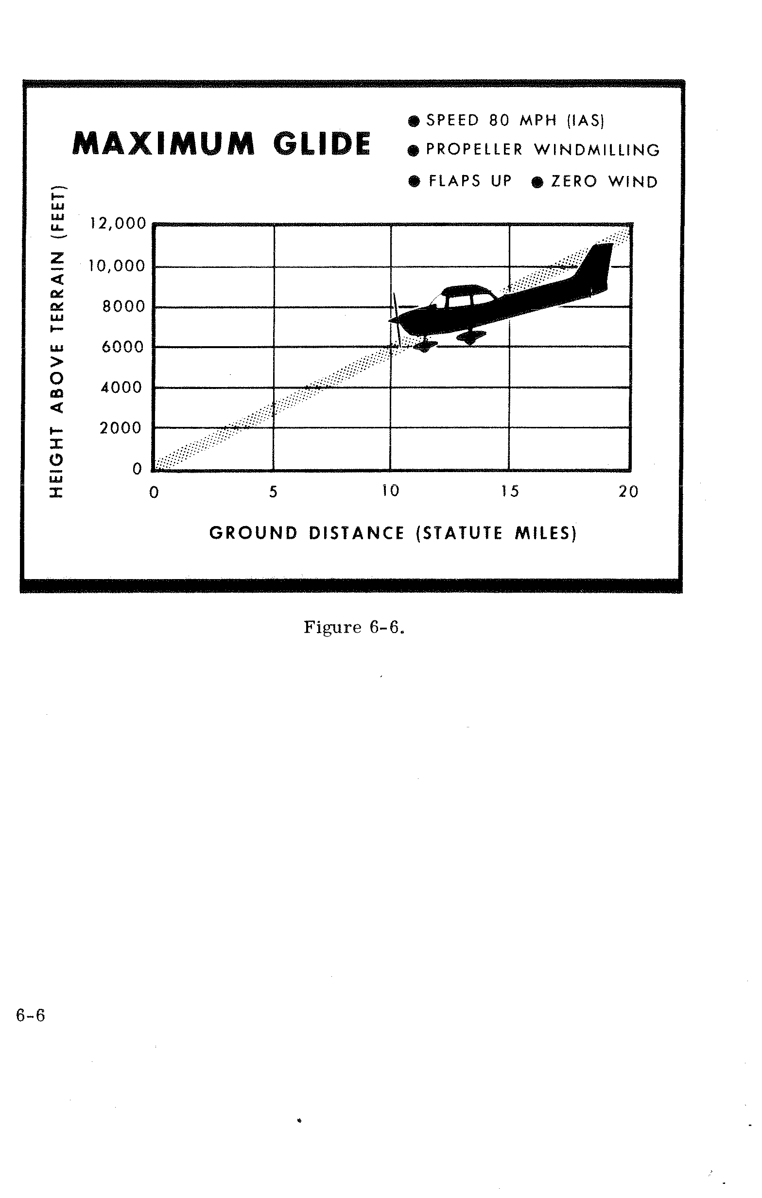
Conditions:
- Speed: 80 MPH (IAS)
- Propeller windmilling
- Flaps up
- Zero wind
| Height Above Terrain (ft) | Approx. Ground Distance (statute miles) |
|---|---|
| 2,000 | ~3.5 |
| 4,000 | ~7.0 |
| 6,000 | ~10.5 |
| 8,000 | ~14.0 |
| 10,000 | ~17.5 |
| 12,000 | ~20.0 |
Figure 6-6.
Section VII — Optional Systems p. 69
This section contains a description, operating procedures, and performance data (when applicable) for some of the optional equipment which may be installed in your Cessna. Owner's Manual Supplements are provided to cover operation of other optional equipment systems when installed in your airplane. Contact your Cessna Dealer for a complete list of available optional equipment.
Long Range Fuel Tanks
Special wings with long range fuel tanks are available to replace the standard wings and fuel tanks for greater endurance and range. When these tanks are installed, the total usable fuel for all flight conditions is 48 gallons.
Cold Weather Equipment
Winterization Kit
For continuous operation in temperatures consistently below 20°F, the Cessna winterization kit, available from your Cessna Dealer, should be installed to improve engine operation. The kit consists of two baffles which attach to the engine air intakes in the cowling, and insulation for the crankcase breather line. Once installed, the crankcase breather insulation is approved for permanent use in both cold and hot weather.
Ground Service Plug Receptacle p. 70
A ground service plug receptacle may be installed to permit use of an external power source for cold weather starting and during lengthy maintenance work on the airplane electrical system (with the exception of electronic equipment).
Just before connecting an external power source (generator type or battery cart), the master switch should be turned on.
The ground service plug receptacle circuit incorporates a polarity reversal protection. Power from the external power source will flow only if the ground service plug is correctly connected to the airplane. If the plug is accidentally connected backwards, no power will flow to the airplane's electrical system, thereby preventing any damage to electrical equipment.
The battery and external power circuits have been designed to completely eliminate the need to "jumper" across the battery contactor to close it for charging a completely "dead" battery. A special fused circuit in the external power system supplies the needed "jumper" across the contacts so that with a "dead" battery and an external power source applied, turning on the master switch will close the battery contactor.
Static Pressure Alternate Source Valve
A static pressure alternate source valve may be installed in the static system for use when the external static source is malfunctioning.
If erroneous instrument readings are suspected due to water or ice in the static pressure lines, the static pressure alternate source valve control knob located below the wing flap switch should be opened, p. 71 thereby supplying static pressure from the cabin. Cabin pressures will vary, however, with open cabin ventilators or windows. The most adverse combinations will result in airspeed and altimeter variations of no more than 2 MPH and 15 feet, respectively.
Radio Selector Switches
Radio Selector Switch Operation
Operation of the radio equipment is normal as covered in the respective radio manuals. When more than one radio is installed, an audio switching system is necessary. The operation of this switching system is described below.
Transmitter Selector Switch
The transmitter selector switch, labeled TRANS, has two positions. When two transmitters are installed, it is necessary to switch the microphone input to the desired transmitter by selecting position 1 or 2 on the TRANS switch.
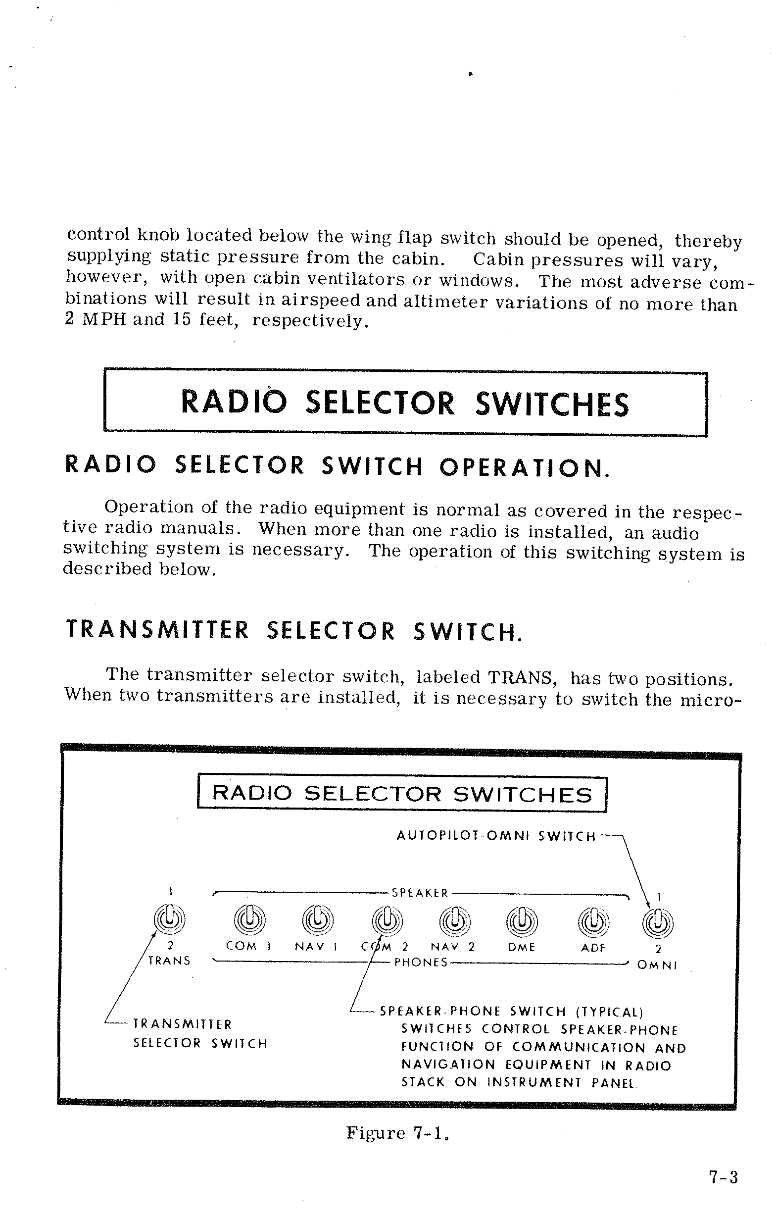
Speaker Phone Switches p. 72
The speaker-phone switches determine whether the output of the receiver in use is fed to the headphones or through the audio amplifier to the speaker. Place the switch for the desired receiving system either in the up position for speaker operation or in the down position for headphones.
Autopilot-Omni Switch
When a Nav-O-Matic autopilot is installed with two compatible omni receivers, an autopilot-omni switch is utilized. This switch selects the omni receiver to be used for the omni course sensing function of the autopilot. The up position selects the upper omni receiver in the radio panel stack and the down position selects the lower omni receiver.
Boom Microphone
A boom microphone may be mounted near the upper left corner of the windshield. Use of the boom microphone allows radio communication without the necessity of releasing any controls to handle the normal hand microphone. The microphone keying switch is a push button located on the left side of the pilot's control wheel.
Wing Leveler p. 73
A wing leveler may be installed to augment the lateral stability of the airplane. The system uses the Turn Coordinator for roll and yaw sensing. Vacuum pressure, from the engine-driven vacuum pump, is routed from the Turn Coordinator to cylinder-piston servo units attached to the aileron control system. As the aircraft deviates from a wing level attitude, vacuum pressure in the servo units is increased or relieved as needed to actuate the ailerons to oppose the deviations.
A separately mounted push-pull control knob, labeled WING LVLR, is provided on the left side of the instrument panel to turn the system on and off. A ROLL TRIM control knob on the Turn Coordinator is used for manual roll trim control to compensate for asymmetrical loading of fuel and passengers, and to optimize system performance in climb, cruise and let-down.
Wing Leveler — Operating Check List
Take-Off
- WING LVLR Control Knob — Check in off position (full in).
Climb
- Adjust elevator trim for climb.
- WING LVLR Control Knob — Pull control knob ON.
- ROLL TRIM Control Knob — Adjust for wings level attitude.
Cruise
- Adjust power and elevator trim for level flight.
- ROLL TRIM Control Knob — Adjust as desired.
Descent
- Adjust power and elevator trim for desired speed and rate of descent.
- ROLL TRIM Control Knob — Adjust as desired.
Landing p. 74
- Before landing, push WING LVLR control knob full in to the off position.
Wing Leveler — Emergency Procedures
If a malfunction should occur, the system is easily overpowered with pressure on the control wheel. The system should then be turned off. In the event of partial or complete vacuum failure, the wing leveler will automatically become inoperative. However, the Turn Coordinator used with the wing leveler system will not be affected by loss of vacuum since it is designed with a "back-up" system enabling it to operate from either vacuum or electrical power in the event of failure of one of these sources.
Wing Leveler — Operating Notes
- The wing leveler system may be overpowered at any time without damage or wear. However, for extended periods of maneuvering it may be desirable to turn the system off.
- It is recommended that the system not be engaged during take-off and landing. Although the system can be easily overpowered, servo forces could significantly alter the manual "feel" of the aileron control, especially should a malfunction occur.
True Airspeed Indicator p. 75
A true airspeed indicator is available to replace the standard airspeed indicator in your airplane. The true airspeed indicator has a calibrated rotatable ring which works in conjunction with the airspeed indicator dial in a manner similar to the operation of a flight computer.
TO OBTAIN TRUE AIRSPEED, rotate ring until pressure altitude is aligned with outside air temperature in degrees Fahrenheit. Then read true airspeed on rotatable ring opposite airspeed needle.
Fuel Tank Quick-Drain Valve Kit
Two fuel tank quick-drain valves and a fuel sampler cup are available as a kit to facilitate daily draining and inspection of fuel in the main tanks for the presence of water and sediment. The valves replace existing fuel tank drain plugs located at the lower inboard area of the wing. The fuel sampler cup, which may be stowed in the map compartment, is used to drain the valves. The sampler cup has a probe in the center of the cup. When the probe is inserted into the hole in the bottom of the drain valve and pushed upward, fuel flows into the cup to facilitate visual inspection of the fuel. As the cup is removed, the drain valve seats, stopping the flow of fuel.
Oil Quick-Drain Valve p. 76
An oil quick-drain valve is optionally offered to replace the drain plug in the oil sump drain port. The valve provides a quicker and cleaner method of draining engine oil. To drain the oil with this valve installed, slip a hose over the end of the valve, route the hose to a suitable container, then push upward on the end of the valve until it snaps into the open position. Spring clips will hold the valve open. After draining, use a screwdriver or suitable tool to snap the valve into the extended (closed) position and remove the drain hose.
Carburetor Air Temperature Gage
A carburetor air temperature gage may be installed in the aircraft to help detect carburetor icing conditions. The gage is marked with a yellow arc between -15° and +5°C. The yellow arc indicates the carburetor temperature range where carburetor icing can occur; a placard on the gage reads KEEP NEEDLE OUT OF YELLOW ARC DURING POSSIBLE ICING CONDITIONS.
Visible moisture or high humidity can cause carburetor ice formation, especially in idle or low power conditions. Under cruising conditions, the formation of ice is usually slow, providing time to detect the loss of RPM caused by the ice. Carburetor icing during take-off is rare since the full-open throttle condition is less susceptible to ice obstruction.
If the carburetor air temperature gage needle moves into the yellow arc during potential carburetor icing conditions, or there is an unexplained drop in RPM, apply full carburetor heat. Upon regaining the original RPM (with heat off), determine by trial and error the minimum amount of carburetor heat required for ice-free operation.
Servicing Requirements p. 79
Fuel
| Item | Specification / Value |
|---|---|
| Grade | Aviation Grade — 80/87 Minimum Grade |
| Capacity — Each Standard Tank | 21 Gallons |
| Capacity — Each Long Range Tank | 26 Gallons |
Engine Oil
| Temperature Range | Recommended Grade |
|---|---|
| Above 60°F | SAE 50 |
| Between 0° and 70°F | SAE 10W30 or SAE 30 |
| Below 10°F | SAE 10W30 or SAE 20 |
| Item | Value |
|---|---|
| Capacity of Engine Sump | 8 Quarts |
| Minimum Operating Level | 6 Quarts |
| Fill level — Normal flights (less than 3 hours) | 7 Quarts |
| Fill level — Extended flight | 8 Quarts |
Hydraulic Fluid
MIL-H-5606 Hydraulic Fluid
Tire Pressures
| Wheel | Tire Size | Pressure (PSI) |
|---|---|---|
| Nose Wheel | 5.00 - 5, 4 Ply Rated | 31 PSI |
| Nose Wheel | 6.00 - 6, 4 Ply Rated | 26 PSI |
| Main Wheels | 6.00 - 6, 4 Ply Rated | 29 PSI |
Nose Gear Shock Strut
Keep filled with hydraulic fluid and inflated with air to 45 PSI.
CESSNA AIRCRAFT COMPANY
Wichita, Kansas
"Take your Cessna home for service at the sign of the Cessna Shield"
CESSNA
"TAKE YOUR CESSNA HOME
FOR SERVICE AT THE SIGN
OF THE CESSNA SHIELD"
CESSNA AIRCRAFT COMPANY
WICHITA, KANSAS
This section has not been processed yet.